Essential Idea:
Generation and transmission of alternating current (ac) electricity has transformed the world.
Understandings:
- Alternating current (ac) generators
- Average power and root mean square (rms) values of current and voltage
- Transformers
- Diode bridges
- Half-wave and full-wave rectification
Applications and Skills:
- Explaining the operation of a basic ac generator, including the effect of changing the generator frequency
- Solving problems involving the average power in an ac circuit
- Solving problems involving step-up and step-down transformers
- Describing the use of transformers in ac electrical power distribution
- Investigating a diode bridge rectification circuit experimentally
- Qualitatively describing the effect of adding a capacitor to a diode bridge rectification circuit
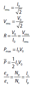
Data booklet reference:
ALTERNATING AND DIRECT CURRENT
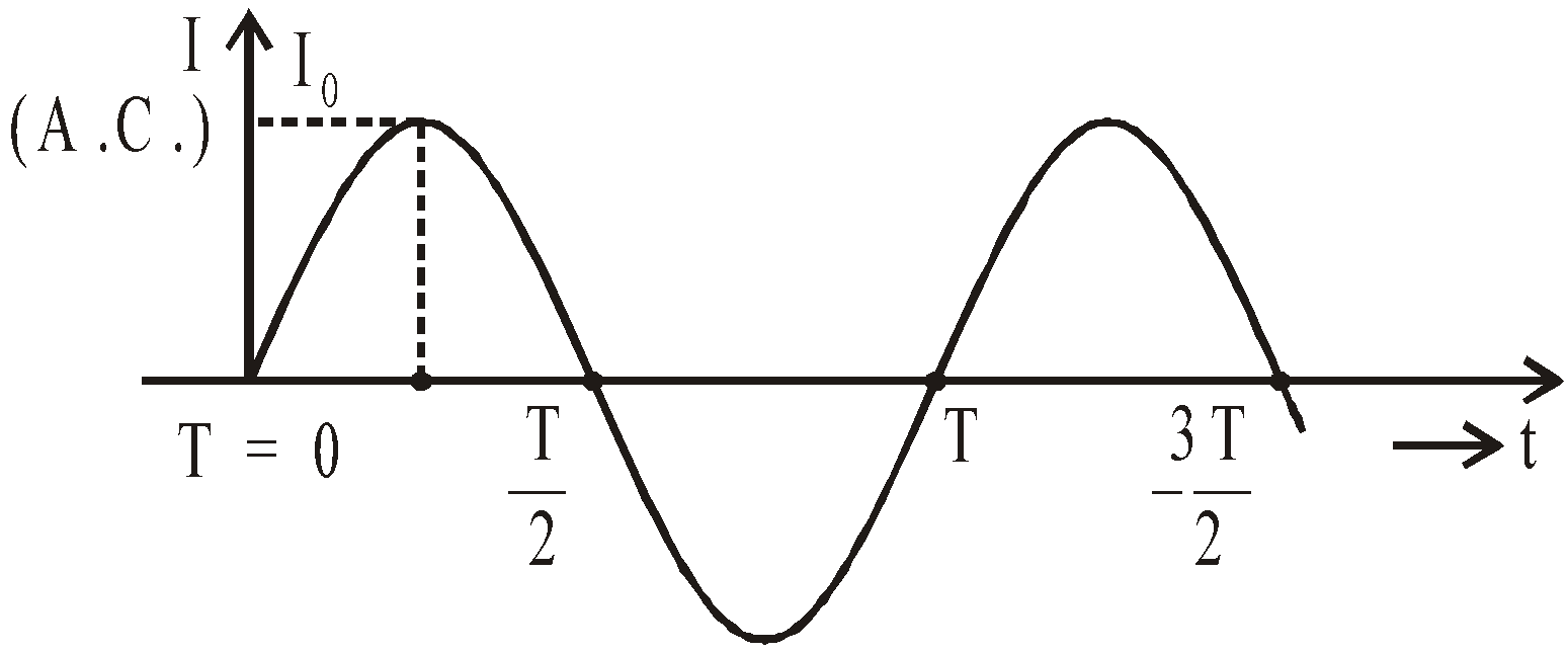
An alternating current (A.C.) is one which periodically changes in magnitude and direction. It increases from zero to a maximum value, then decreases to zero and reverses in direction, increases to a maximum in this direction and then decreases to zero.
The source of alternating emf may be a dynamo or an electronic oscillator.
The alternating emf E at any instant may be expressed as
E = E0 sinωt
where ω is the angular frequency of alternating emf and E0 is the peak value of emf.
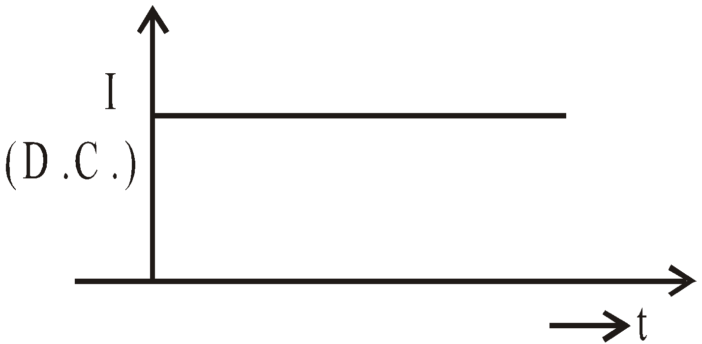
Direct current (D.C.) is that current which may or may not change in magnitude but it does not change its direction.
ADVANTAGES OF A.C. OVER D.C.
- The generation of A.C. is cheaper than that of D.C.
- Alternating voltage can be easily stepped up or stepped down by using a transformer.
- A.C. can be easily converted into D.C. by rectifier. D.C. is converted to A.C. by an inverter.
- A.C. can be transmitted to a long distance without appreciable loss.
AC GENERATOR, OR AC DYNAMO
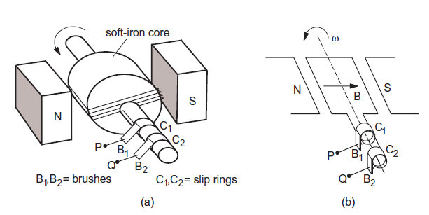
emf Induced as the Coil Rotates
\(\phi=BA\;cos\;\omega t\)
\(-\frac{d\phi}{dt}=BAw\;sin\;\omega t\)
Total emf induced in the coil is
\(\varepsilon = NBA\omega \; sin\;wt = \varepsilon_0\; sin\;\omega t \)
where peak emf \(= NBA\omega\) , angular frequency \(\omega\) and time period \(T =\frac{2\pi}{\omega}\)
AVERAGE AND RMS VALUE OF ALTERNATING CURRENT
The average value of AC over one full cycle is zero since there are equal positive and negative half cycles.
The average current for half cycle is 2I0 /π where I0 is the peak value of current.
The root mean square (rms) value of AC is 
where I0 is the peak or maximum value of alternating current.
The rms value of alternating current can also be defined as the direct current which produces the same heating effect in a given resistor in a given time as is produced by the given A.C. flowing through same resistor for the same time. Due to this reason the rms value of current is also known as effective or virtual value of current.
∴ 
Similarly the rms value of alternating voltage is called the effective or virtual value of alternating voltage (or emf).
∴ 
KEEP IN MEMORY
- Time period : The time taken by A.C. to go through one cycle of changes is called its period. It is given as

- Phase : It is that property of wave motion which tells us the position of the particle at any instant as well as its direction of motion. It is measured either by the angle which the particle makes with the mean position or by fraction of time period.
- Phase angle : Angle associated with the wave motion (sine or cosine) is called phase angle.
- Lead : Out of the current and emf the one having greater phase angle will lead the other e.g., in equation
i = i0 sin and e = e0 sin ωt,
the current leads the emf by an angle  .
.
- Lag : Out of current and emf the one having smaller phase angle will lag the other. In the above equations, the emf lags the current by
 .
.
RESISTANCE OFFERED BY VARIOUS ELEMENTS (INDUCTOR, RESISTOR AND CAPACITOR) TO A.C.
Alternating current in a circuit may be controlled by resistance, inductance and capacitance, while the direct current is controlled only by resistance.
IMPEDANCE (Z)
In alternating current circuit, the ratio of emf applied and consequent current produced is called the impedance and is denoted by Z,
i.e., 
Physically impedance of ac circuit is the hindrance offered by resistance along with either inductance or capacitance or both in the circuit to the flow of ac through it. Its unit is ohm.
REACTANCE (X)
The hindrance offered by inductance or capacitance or both to the flow of ac in an ac circuit is called reactance and is denoted by X. Thus when there is no ohmic resistance in the circuit, the reactance is equal to impedance. The reactance due to inductance alone is called inductive reactance and is denoted by XL, while the reactance due to capacitance alone is called the capacitive reactance and is denoted by XC. Its unit is also ohm.
ADMITTANCE (Y)
The inverse of impedance is called the admittance and is denoted by Y, i.e., 
Its SI unit is ohm–1.
IMPEDANCES AND PHASES OF AC CIRCUIT CONTAINING DIFFERENT ELEMENTS
As already pointed out that in an ac circuit the current and applied emfs are not necessarily in same phase. The applied emf (E) and current produced (I) may be expressed as
E = E0 sin ωt and I = I0 sin (ωt + φ) with I0 = E0 / Z
where E0 and I 0 are peak values of alternating emf and current.
CIRCUIT CONTAINING ONLY RESISTOR (R)
Consider a pure ohmic resistor (zero inductance) of resistance R connected to an alternating source of emf E = E0 sinωt.
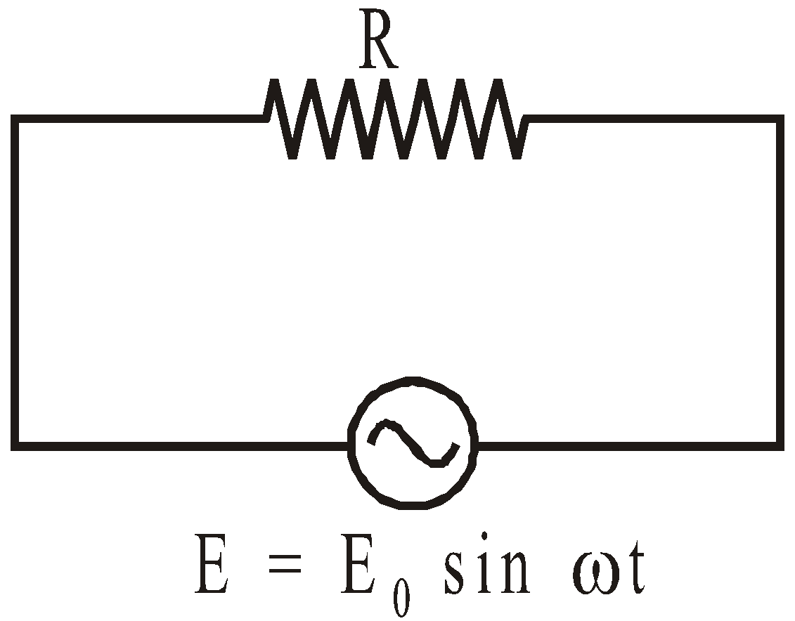
Then current I in the circuit is
Comparing this with standard equation, we get that impedance of circuit, Z = R and phase difference between current & emf = 0.
Hence we conclude that in a purely resistive ac circuit the current and voltage are in same phase and impedance of circuit is equal to the ohmic resistance.
Phasor diagram :

Graph of emf or current versus ωt :

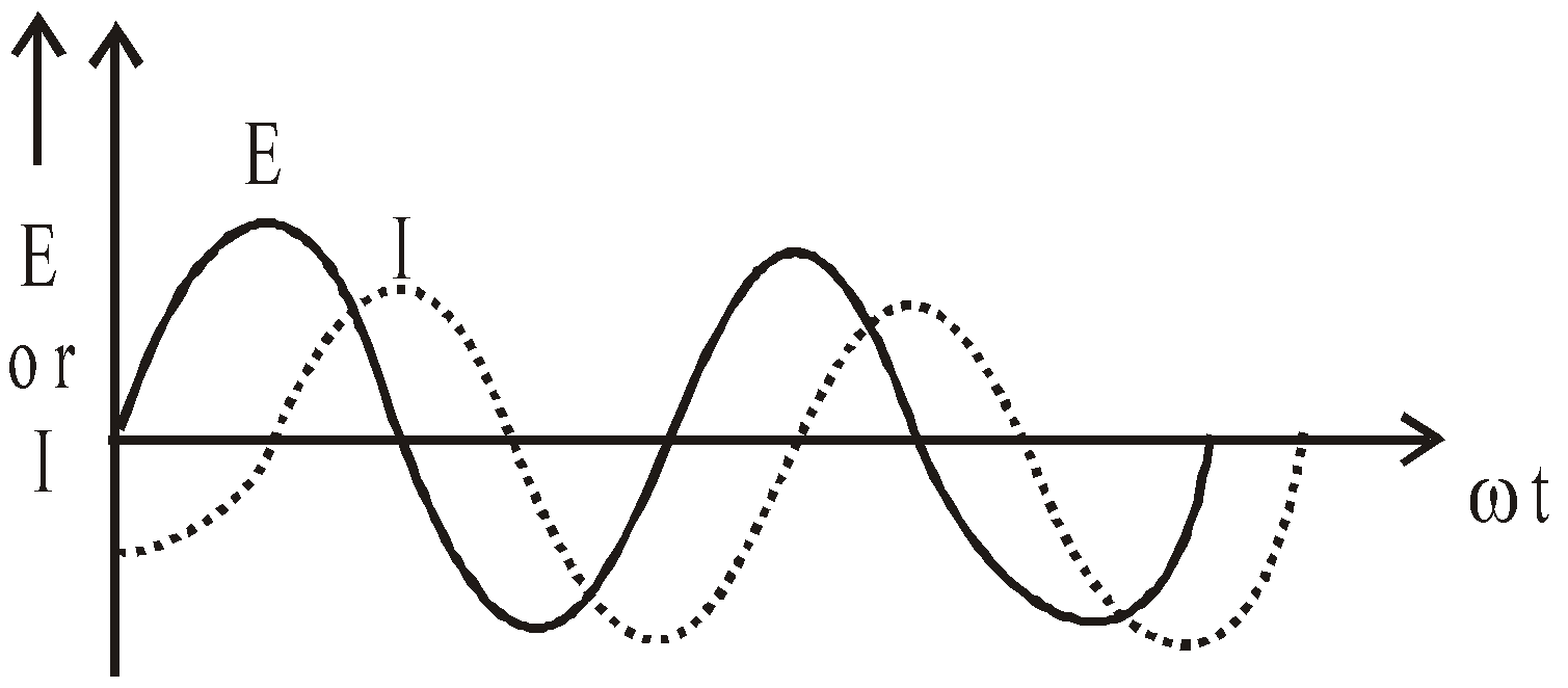
CIRCUIT CONTAINING ONLY INDUCTOR (L)
Consider a pure inductor (zero ohmic resistance) of inductance L connected to an alternating source of emf E = E0 sin ωt.
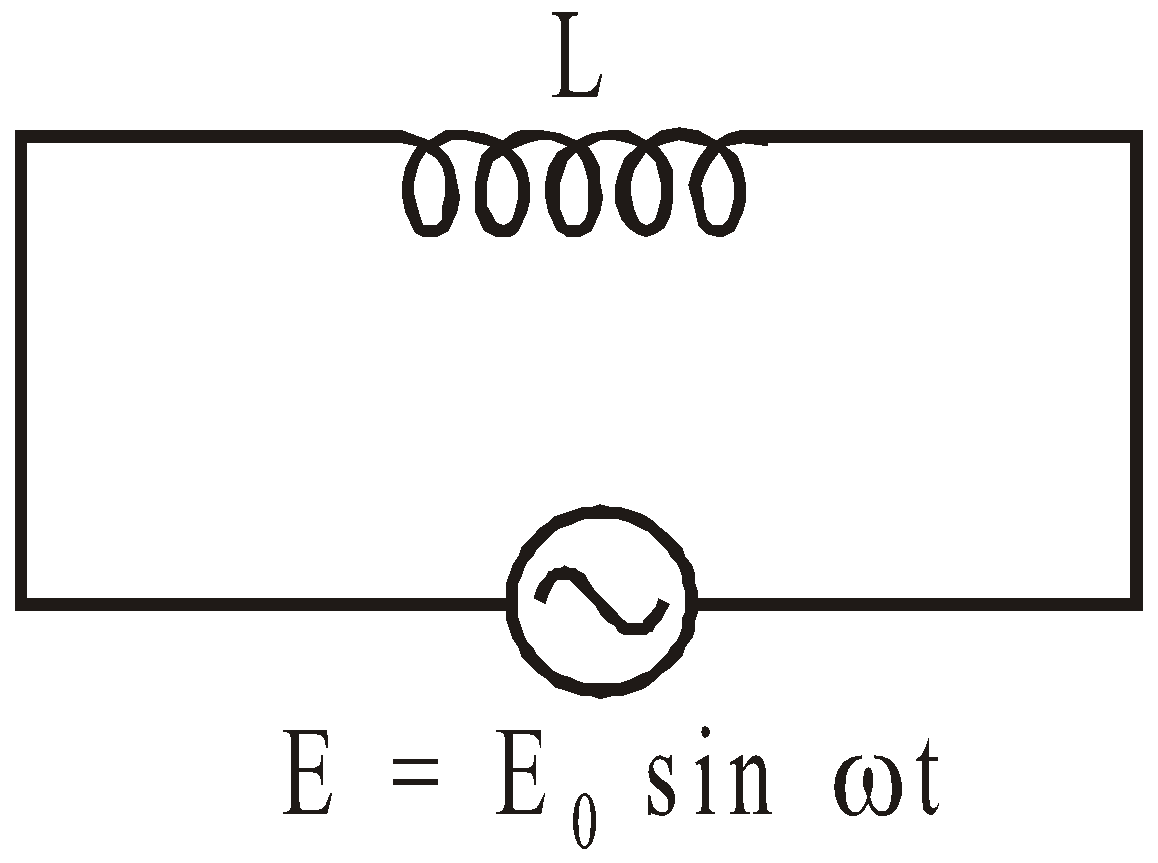
Then current I in the circuit is
Comparing this with standard equation, we get
Z = ω L and phase difference φ = π/2.
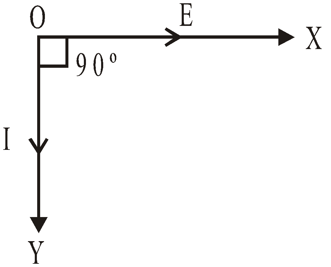
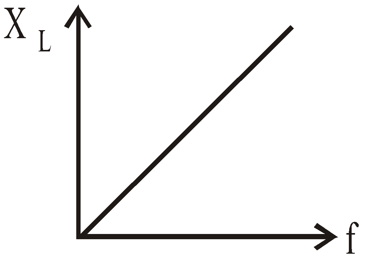
Hence we conclude that in a purely inductive circuit the current lags behind the applied voltage by an angle π/2 and the impedance to the circuit is ωL and this is called as inductive reactance.
Graph of emf or current versus ωt
Phasor diagram
Graph between XL and f
CIRCUIT CONTAINING ONLY CAPACITOR (C)
Consider a capacitor of capacitance C connected to an alternating source of emf,
E = E0 sin ωt.
E = E0 sin ωt.
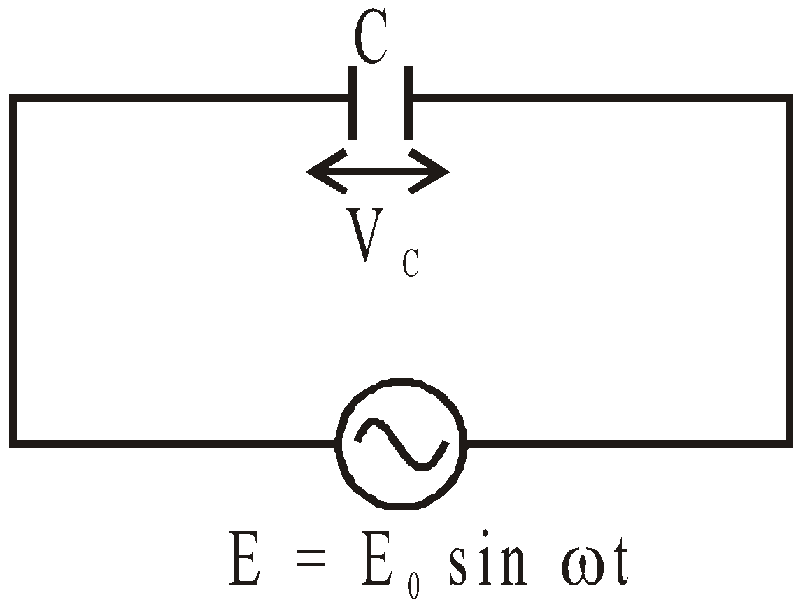
Then the current through capacitor is given by,
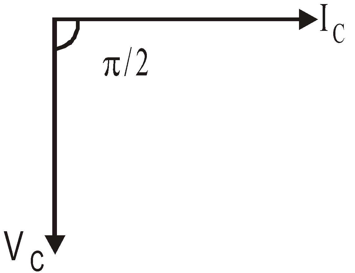
Comparing this with standard equation, we find that capacitive reactance XC = 1/ωC and phase difference φ = + π/2
Phasor diagram
Graph between XC and f
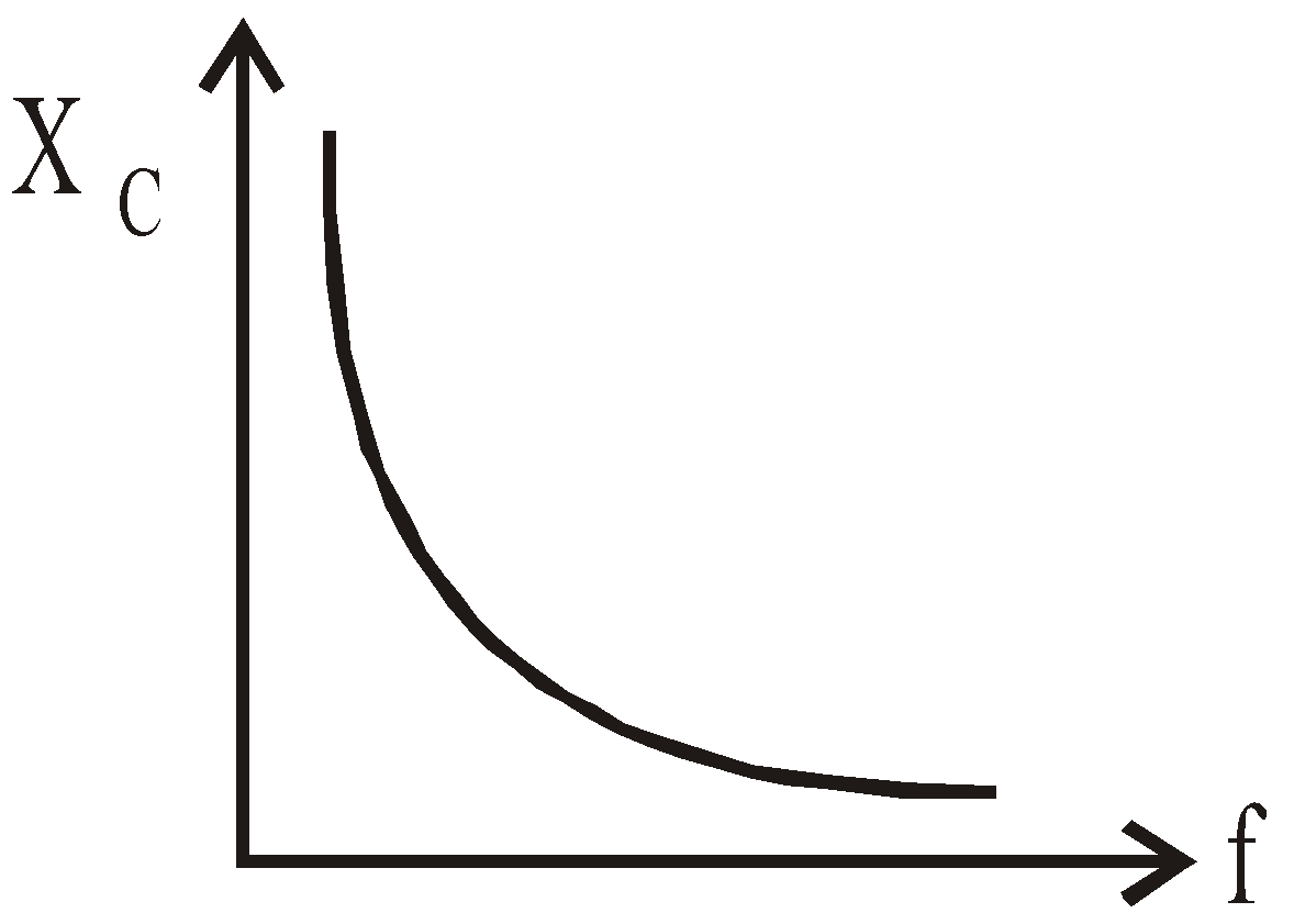
Hence we conclude that in a purely capacitive circuit the current leads the applied emf by an angle π/2 and the impedance of the circuit is 1/ωC and this is known as capacitive reactance.
Graph of emf or current versus ωt
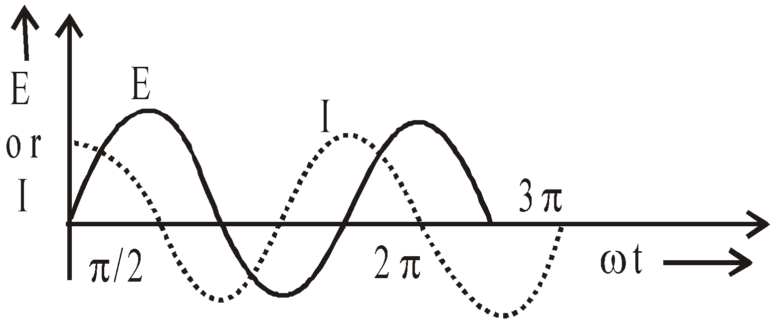
CIRCUIT CONTAINING RESISTANCE AND INDUCTANCE IN SERIES (L-R SERIES CIRCUIT)
Consider a circuit containing resistance R and inductance L in series having an alternating emf E = E0 sin ωt.
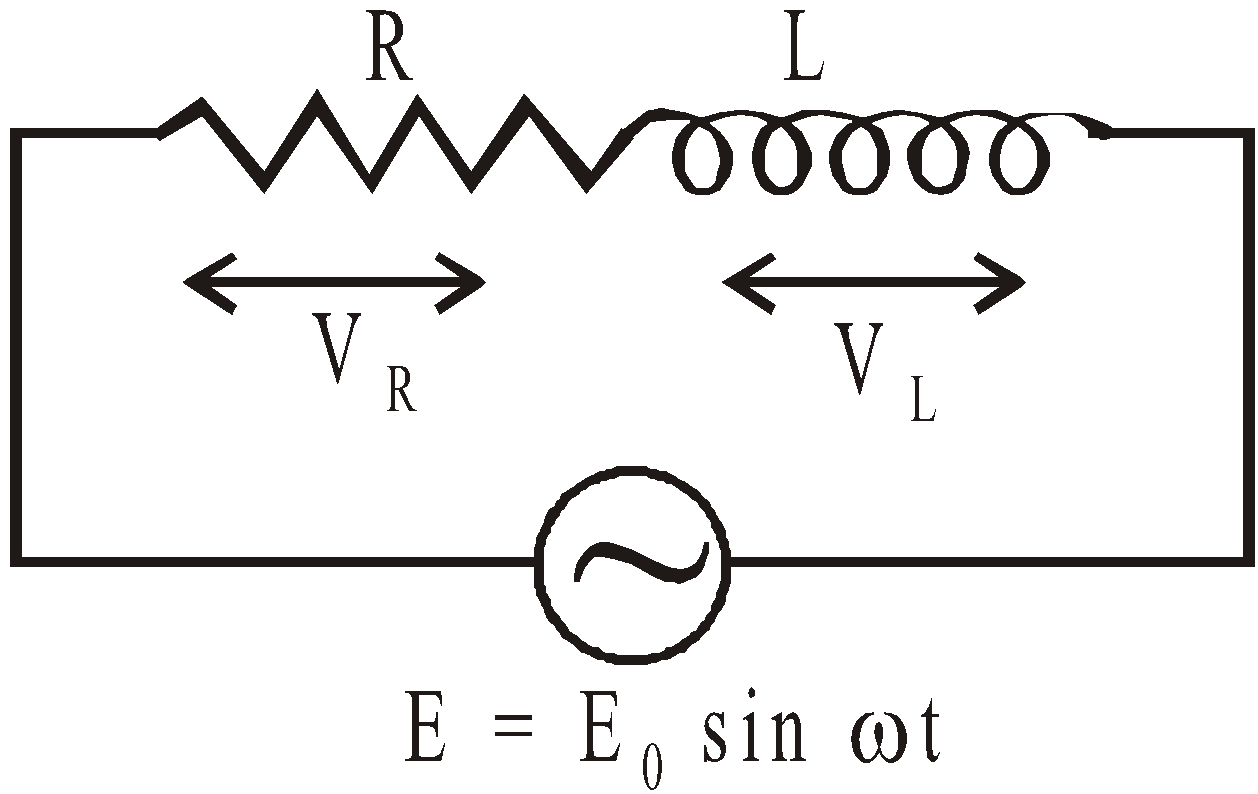
Let I be the current flowing in the circuit and VR (= IR) the potential difference across resistance and VL (= ωL.I) the potential difference across inductance.
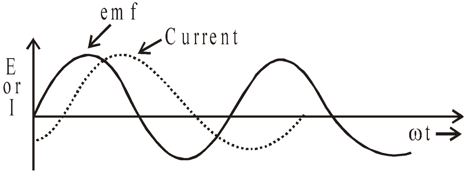
The current I and the potential difference VR are always in phase but the potential difference VL across inductance leads the current I by an angle π/2.
Phasor diagram
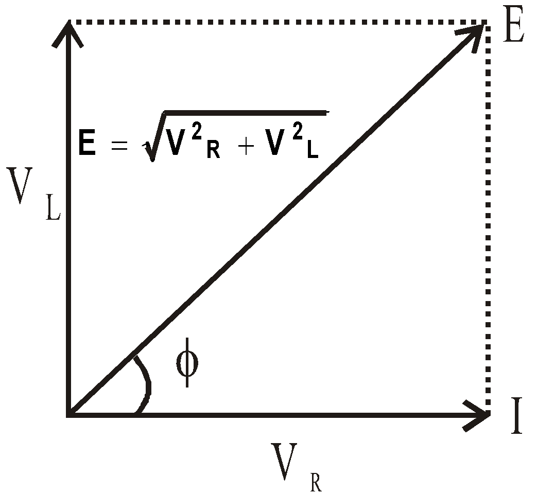
From phasor diagram, resultant voltage is given by,
Graph of emf or current versus ωt
∴ 
∴ Impedance of R – L circuit,
It is obvious that the current lags behind the emf by angle φ given by,
CIRCUIT CONTAINING RESISTANCE AND CAPACITANCE IN SERIES (C–R SERIES CIRCUIT)
Consider a circuit containing resistance R and capacitance C in series having an alternating emf E = E0 sin ωt.
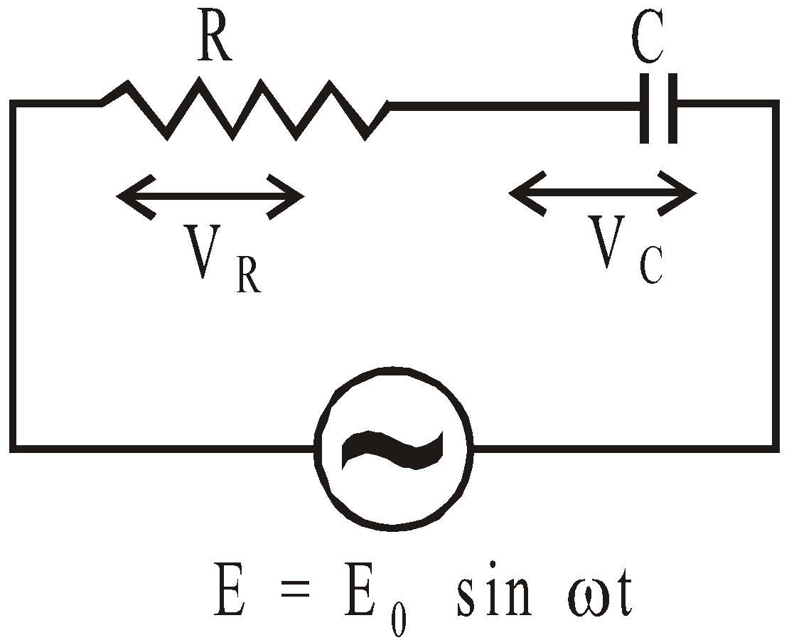
Let Ι be the current flowing in the circuit, VR the potential difference across resistance and VC the potential difference across capacitance.
Phasor diagram
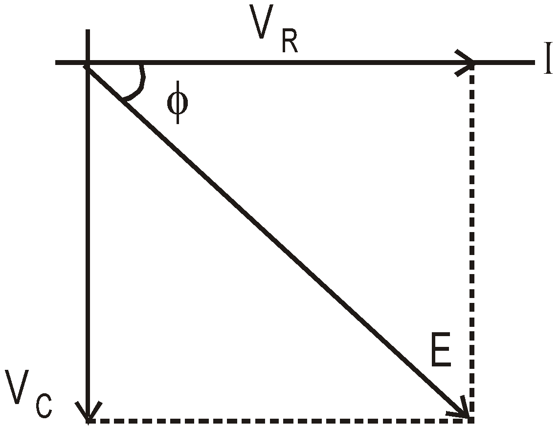
From phasor diagram the resultant emf is given by
∴ Impedance,  , where
The potential difference VR and current I are in same phase and the potential difference VC lags behind the current I (and hence VR) by angle π/2
The current leads the applied emf by an angle φ given by
or 
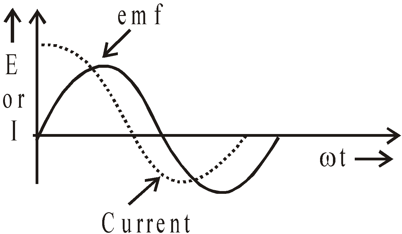
Graph of emf or current versus ωt
CIRCUIT CONTAINING INDUCTANCE AND CAPACITANCE IN SERIES (SERIES L-C CIRCUIT)
Consider a circuit containing inductance L and capacitance C in series having an alternating emf
E = E0 sin ωt.

Let I be the current flowing in circuit, VL the potential difference across inductance L and VC the p.d. across capacitance C.
Phasor diagram
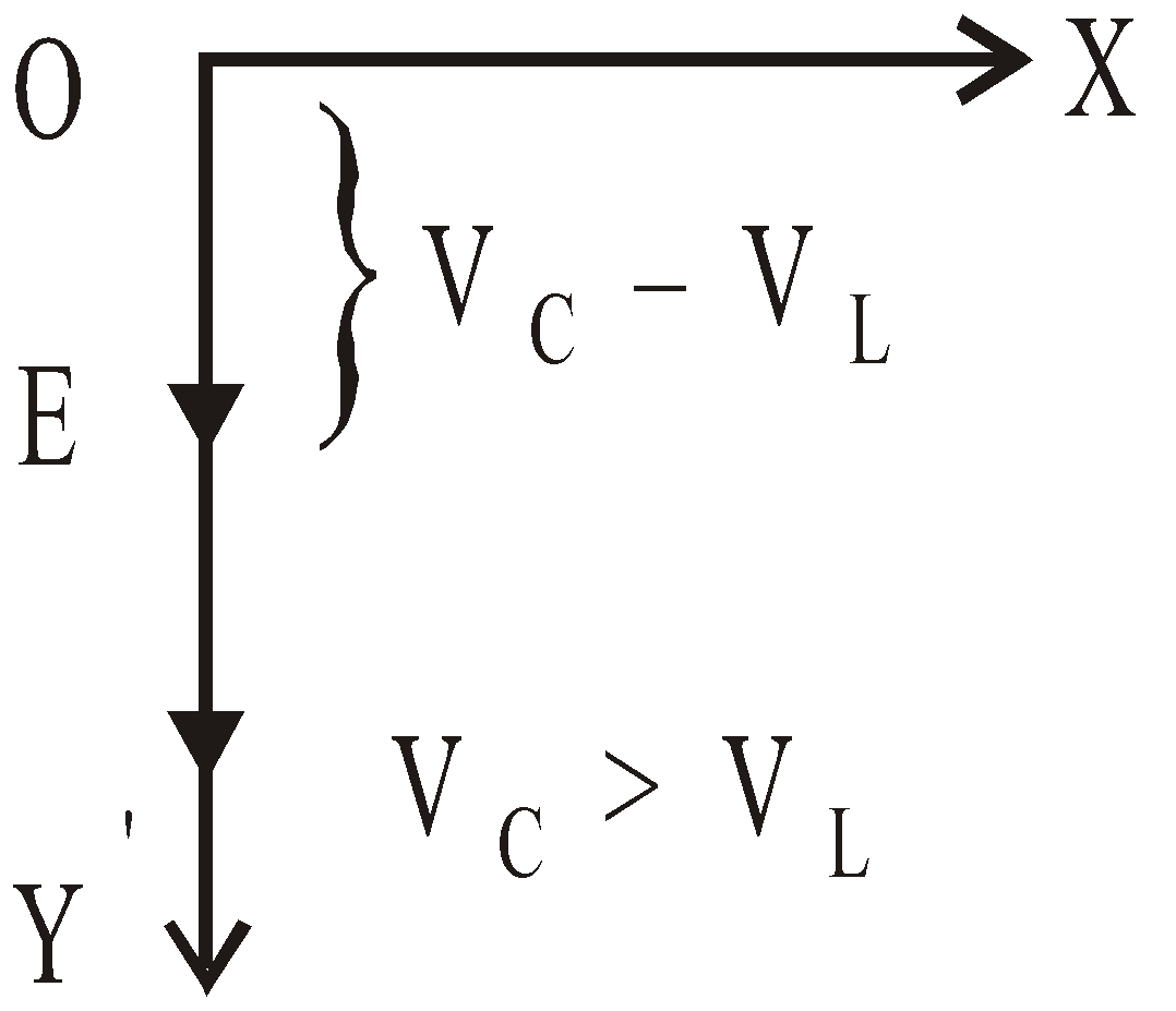
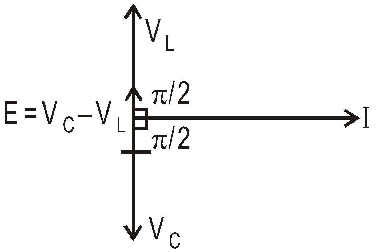
The p.d. VC lags behind the current by angle π/2 and the p.d. VL leads the current by angle π/2.
∴ Resultant applied emf, E = VC – VL = XCI – XLI
∴ Reactance of circuit, 
The current leads applied emf by .
.
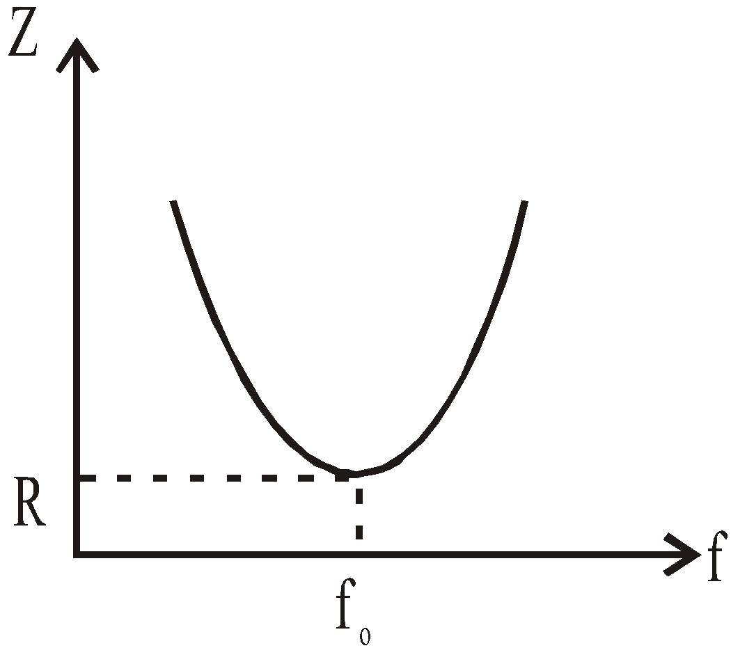
In case of XC = XL, Z = 0, then 
∴ Frequency 
At certain frequency the impedance of the circuit is minimum and the current is maximum.
This frequency is called the resonant frequency.
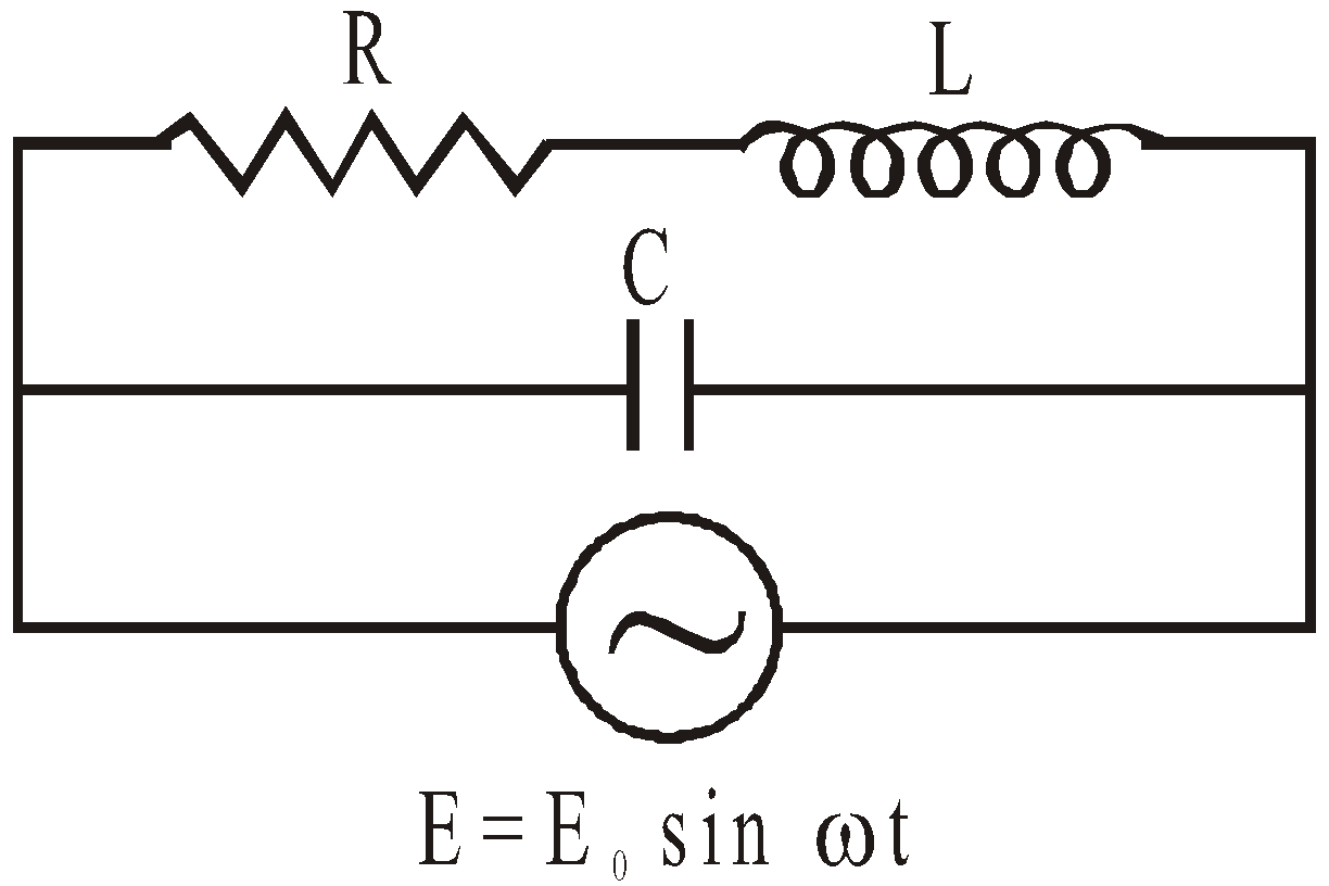
CIRCUIT CONTAINING RESISTANCE, INDUCTANCE AND CAPACITANCE IN SERIES (SERIES LCR CIRCUIT)
Consider a circuit containing a resistance R, inductance L and capacitance C in series having an alternating emf
E = E0 sin ωt.

Let I be the current flowing in circuit. VR, VL and VC are respective potential differences across resistance R, inductance L and capacitance C.
Phasor diagram
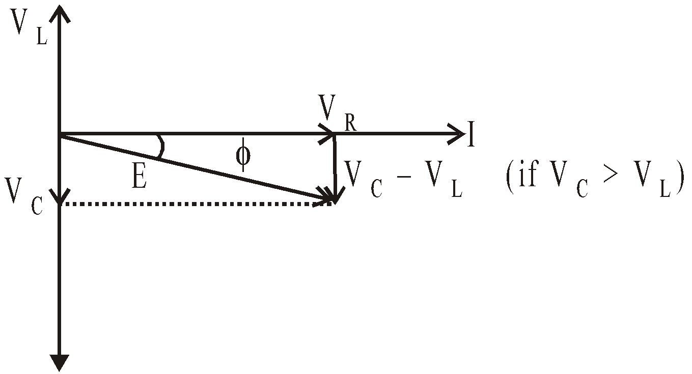
The p.d. VR is in phase with current I . The p.d. VC lags behind the current by angle π/2. The p.d. VL leads the current by angle π/2.
∴ Resultant applied emf, 
i.e., 
∴ Impedance, 
The phase leads of current over applied emf is given by

It is concluded that :
- If XC > XL, the value of φ is positive, i.e., current leads the applied emf.
- If XC < XL, the value of φ is negative, i.e., current lags behind the applied emf.
- If XC = XL, the value of φ is zero, i.e., current and emf are in same phase. This is called the case of resonance and resonant frequency for condition XC = XL, is given by :
∴ 
Thus the resonant frequency depends on the product of L and C and is independent of R.
At resonance, impedance is minimum, Zmin = R and current is maximum 
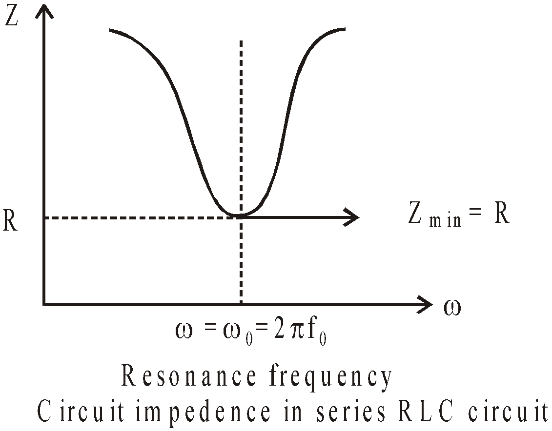
It is interesting to note that before resonance the current leads the applied emf, at resonance it is in phase, and after resonance it lags behind the emf. LCR series circuit is also called as acceptor circuit and parallel LCR circuit is called rejector circuit.
COMMON DEFAULT
🗴 Incorrect. Adding impedances / reactances /resistors algebraically.
✓ Correct. For these physical quantities, vector addition must be done
🗴 Incorrect. Kirchhoff’s laws are applicable in D.C. circuit only
✓ Correct. Kirchhoff’s laws are applicable in A.C. circuit also (which may include inductor and capacitor).
PARALLEL RESONANT CIRCUIT
A parallel resonant circuit consists of an inductance L and a capacitance C in parallel as shown in fig.
The condition of resonance is again that the current and applied emf must be in same phase. The condition gives angular resonant frequency.
∴ Resonant frequency 
The impedance at resonance, 
In parallel resonant circuit the impedance is maximum and the current is minimum.
If  , then
  and
and  .
.
Q – Factor
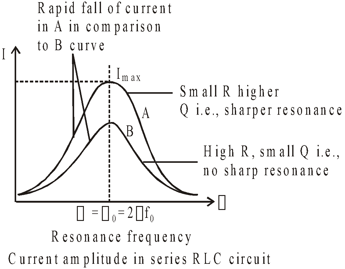
The sharpness of tuning at resonance is measured by
Q-factor or quality factor of the circuit and is given by
Q-factor or quality factor of the circuit and is given by
Higher the value of Q-factor, sharper is the resonance i.e. more rapid is the fall of current from maximum value (I0) with slight change in frequency from the resonance value.
It is clear from the figure that at low value of θ, the resonance is poor. However the bandwidth increases

The figure given below explains the concept of bandwidth and cut-off frequency.
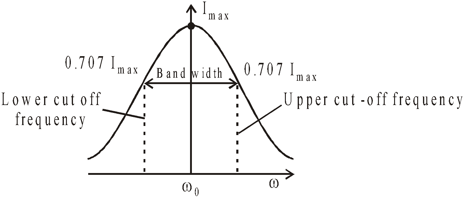

Bandwidth : It is the band of allowed frequencies and is defined as the difference between upper and lower cut-off frequencies, the frequency at which power becomes half of maximum value and current becomes  .
.
POWER IN AN A.C. CIRCUIT
The power is defined as the rate at which work is being done in the circuit. In ac circuit, the current and emf are not necessarily in the same phase, therefore we write
E = E0 sin ωt & I = I0 sin (ωt + φ).
The instantaneous power, P = EI
= E0 sin ωt I0 sin (ωt + φ),
The average power Pav = Erms Irms cos φ
∴ 
In this expression cos φ is known as power factor. The value of cos φ depends on the nature of the circuit. For L, C and
L-C circuit, the power factor is zero ( φ = 90º); for R-circuit
cos φ = 1 ( φ = 0) and for all other circuit cos φ = R/Z, where
Z = impedance.
L-C circuit, the power factor is zero ( φ = 90º); for R-circuit
cos φ = 1 ( φ = 0) and for all other circuit cos φ = R/Z, where
Z = impedance.
If R = 0, cos φ = 0 and Pav = 0 i.e., in a circuit with no resistance, the power loss is zero. Such a circuit is called the wattless circuit and the current flowing is called the wattless current.
Power is of two types

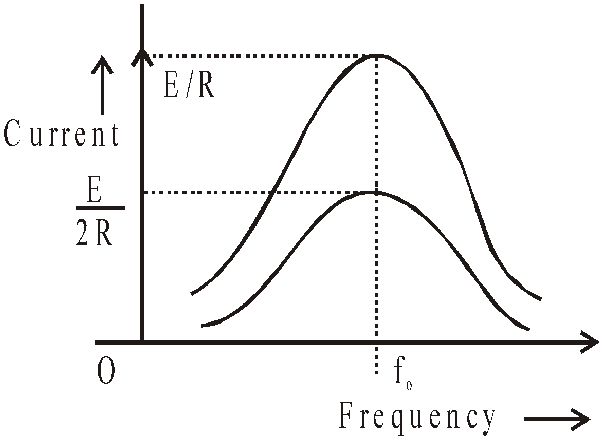
Half Power Points
The values of ω at which the average power is half of its maximum value (at resonant frequency) are called half power points.
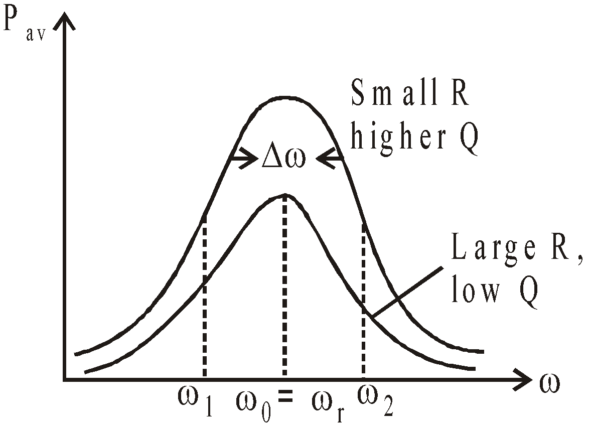
Plot of average power versus frequency for a series RLC circuit. The upper curve is for a small R & lower broad curve is for large value of R.
It is clear from the figure that for smaller R, value of Q0 is high (Q0 is Quality factor of circuit) & hence sharper resonance i.e. greater rate of fall of average power maximum average power Pav changes with slight change in frequency from resonant frequency.
The Quality factor, Q0 is defined as, 
Where Δω = ω2 – ω1 and ω2 & ω1 are half power points.
Now, since ; so
; so 
Whereas ω1 = ω0 ; ω2 = ω0
In concise term, we can write as, 
KEEP IN MEMORY
- Unless mentioned otherwise, all a.c. currents and voltages are r.m.s. values.
- For resonance to occur, the presence of both L and C elements in the circuit is a must.
- In series resonant circuit, current is maximum at resonance. In a parallel resonant circuit, current is minimum (or zero) at resonance but p.d across the combination is maximum.
- To depict oscillatory motion mathematically we may use sines, cosines or their linear combination. This is because changing the zero position transforms one into another.
- While adding voltage across different elements in an a.c. circuit we should take care of their phases.
- The average current over a complete cycle in an a.c circuit is zero but the average power is not zero.
- An inductor offers negligibly low resistance path to d.c. and a resistive path for a.c.
- A capacitor acts as a block for d.c and a low resistance path to a.c.


- The principle of electric meter is heating effect of current. These meters give the reading of Irms. It is important to note that these meters can measure D.C. as well as A.C.
- D.C. flows through the cross-section of the conductor whereas A.C. flows mainly along the surface of the conductor. This is also known as Skin Effect. The skin effect is directly proportional to the frequency.
VARYING CURRENT
When the key in a D.C. circuit (containing a D.C. source of emf, inductance coil, resistance and capacitor) is closed or opened, the current in the circuit varies. This is known as varying current as it varies w.r.t. time and takes a final value after a short while.
GROWTH OF CURRENT
If K is closed at t = 0 so at t = 0, current in the circuit I = 0. After closing the key K at time t let current in the circuit = I and for small time in the circuit, current varies with time,
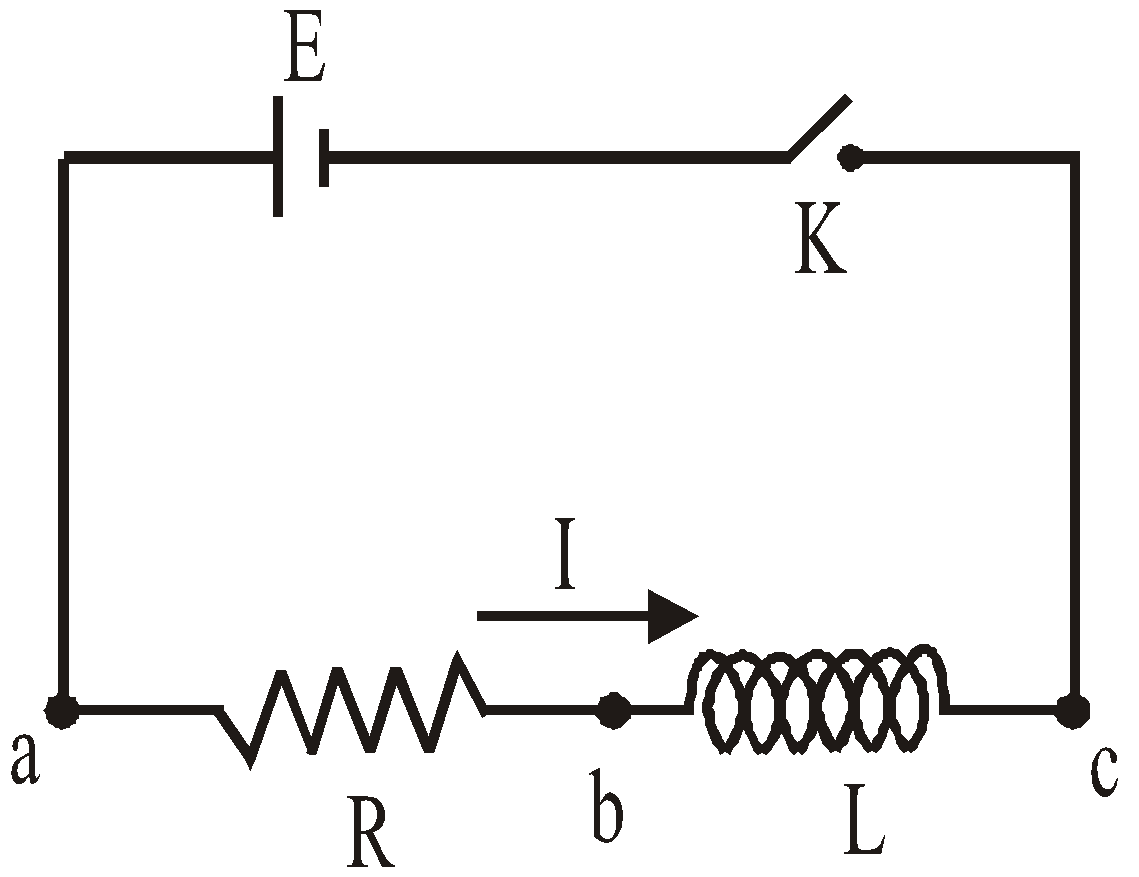
so if rate of change of current with time = 
then due to phenomenon of self induction, induced emf across inductance 
Potential difference across the resistance = IR
During growth of current in L-R circuit, if we applying Kirchhoff’s loop rule then
On solving it we get the value of current at any time t during growth of current in LR-circuit.

GRAPH SHOWING HOW CURRENT VARIES WITH TIME
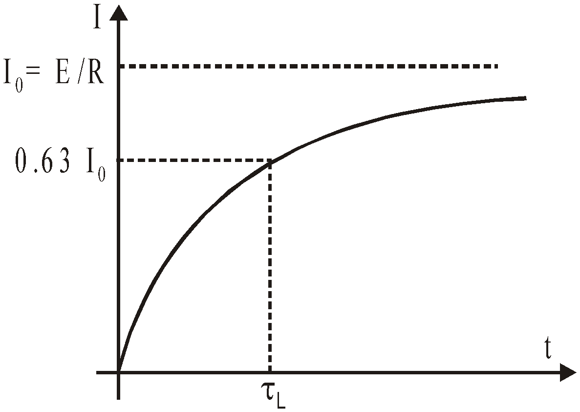
TIME CONSTANT
At t =  ;
;  = Ι0 (1 – e–1) =
=  = 0.632 Ι0
The inductive time constant of an LR-circuit is the time in which the current grows from zero to 0.632 (or 63.2%) of its maximum value. When t → ∞.
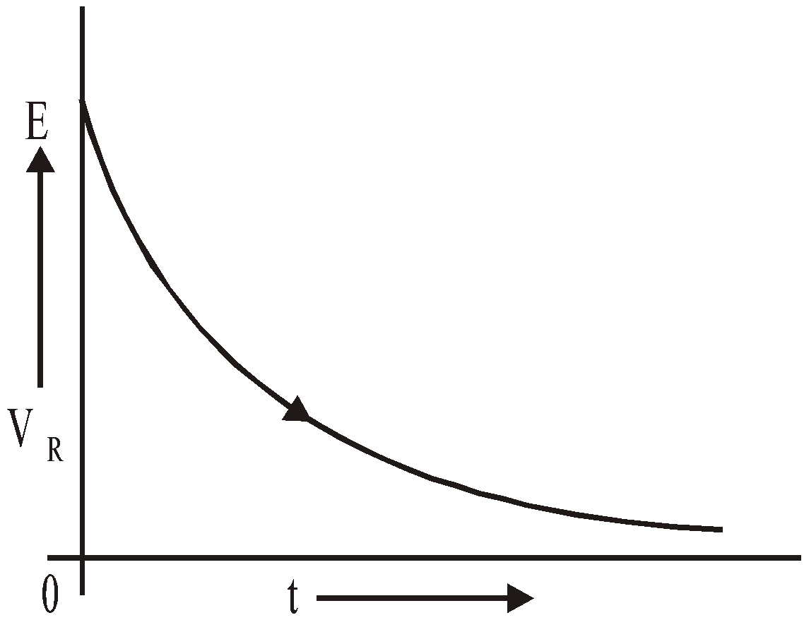
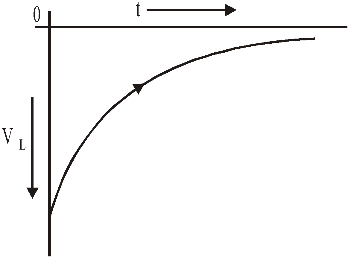
POTENTIAL DIFFERENCE ACROSS RESISTANCE
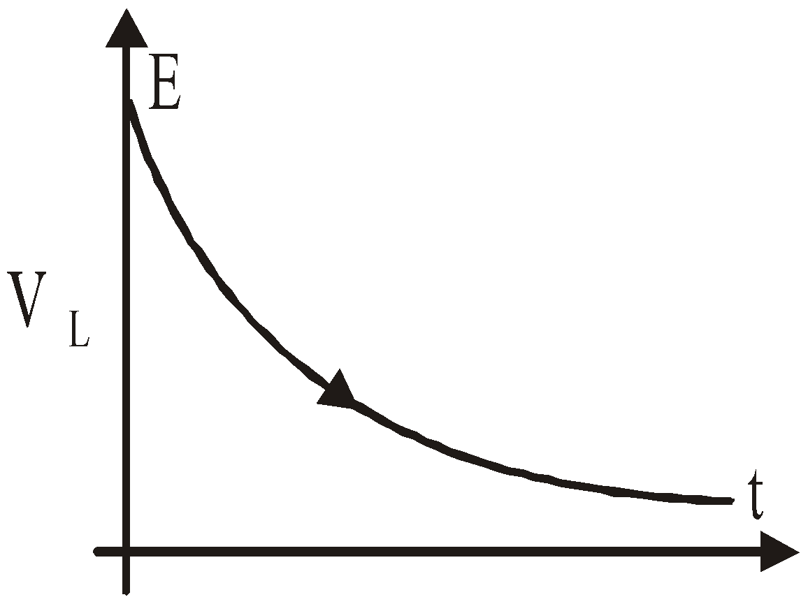
VR =  ; VL =
VL = 
Initially, an inductor acts to oppose changes in the current through it. A long time later, it acts like ordinary connecting wire.
DECAY OF CURRENT
Let the current has reached its steady state value Ι0 through inductor. Now switch K in the circuit shown in fig. has been closed.
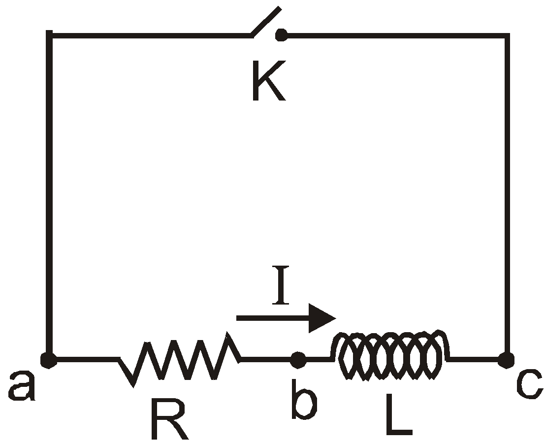
Let this time is t = 0.
Let at t = 0 current in the circuit (which is maximum) = Ι0
After time t current in the circuit = Ι
Applying Kirchhoff’s loop rule to this circuit
or  or
or 
The eqn. gives the value of current at any time t during decay of current in LR-circuit.
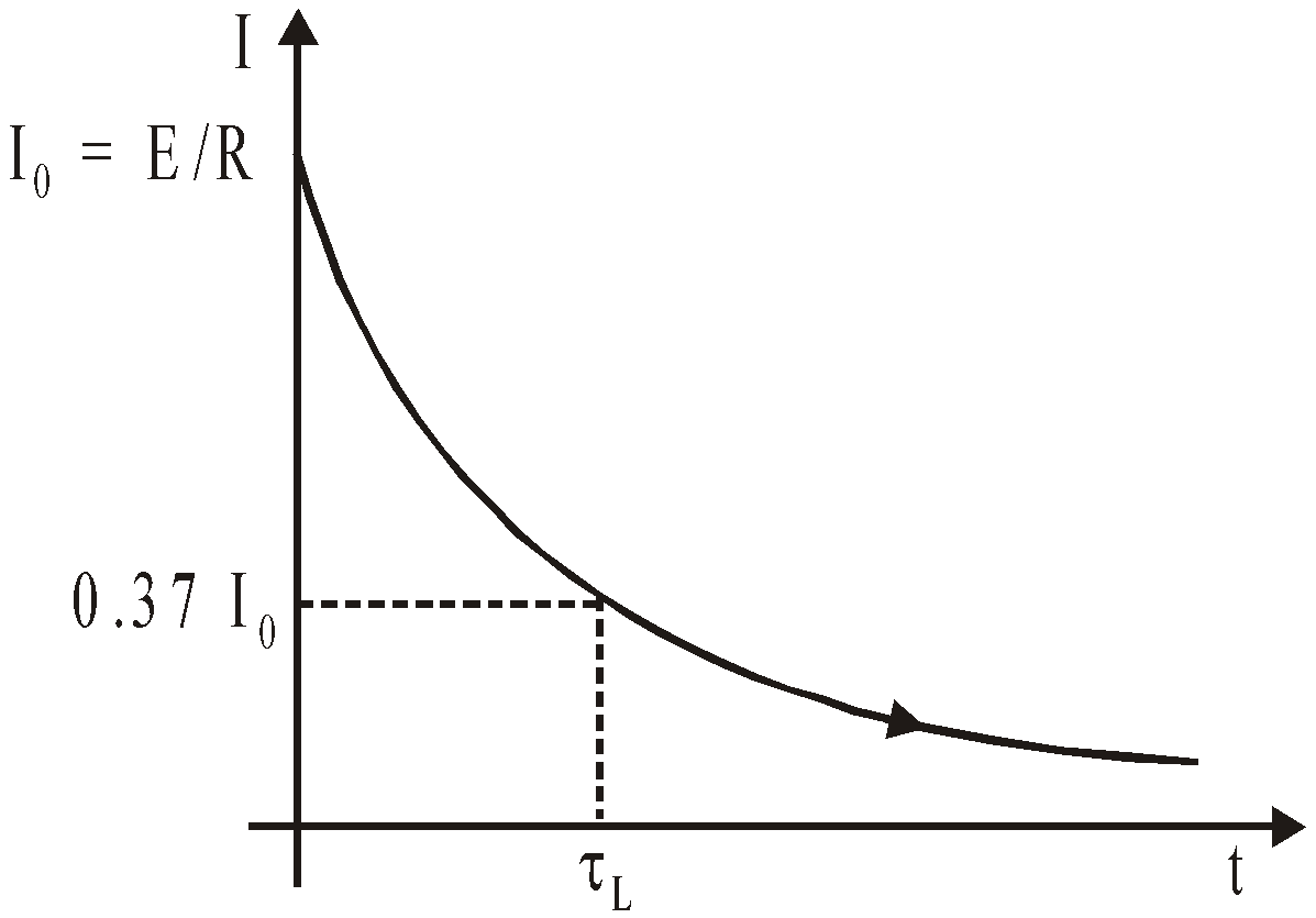
Again, dimensions of  are same as that of time
The inductive time constant of the LR-circuit can also be defined by using equation
Setting  in equation, we get
As t → ∞, Ι → 0
VR = ΙR
or  VL =
VL = 

LC OSCILLATIONS
If a charged capacitor C is short-circuited through an inductor L, the charge and current in the circuit start oscillating simple harmonically. If the resistance of the circuit is zero, no energy is dissipated as heat. Assume an idealized situation in which energy is not radiated away from the circuit. With these idealizations-zero resistance and no radiation, the oscillations in the circuit persist indefinitely and the energy is transferred from the capacitor’s electric field to the inductor’s magnetic field back and forth. The total energy associated with the circuit is constant. This is analogous to the transfer of energy in an oscillating mechanical system from potential energy to kinetic energy and back, with constant total energy.
Let us now derive an equation for the oscillations in an L-C circuit.


Refer figure (a) : The capacitor is charged to a potential difference V such that charge on capacitor q0 = CV
Here q0 is the maximum charge on the capacitor. At time t = 0, it is connected to an inductor through a switch S. At time t = 0, switch S is closed.
Refer figure (b) : When the switch is closed, the capacitor starts discharging. Let at time t charge on the capacitor is q (< q0) and since, it is further decreasing there is a current i in the circuit in the direction shown in figure.
The potential difference across capacitor = potential difference across inductor,
or Vb – Va = Vc – Vd ∴ …(i)
…(i)
Now, as the charge is decreasing,
Substituting this  value of in equation (i), we get
This is the standard equation of simple harmonic motion

Here  or
or  …(iii)
The general solution of equation (ii),
is 
In case φ = 0 as q = q0 at t = 0.
Thus, we can say that charge in the circuit oscillates with angular frequency given by equation (iii). Thus, in L-C oscillations, q, i and  all oscillate harmonically with same angular frequency ω. But the phase difference between q and i or between i and
  is π/2. Their amplitudes are q0, q0ω and ω2q0 respectively.
So q = q0cosωt, then
So q = q0cosωt, then
Similarly potential energy across capacitor (UC) and across inductor (UL) also oscillate with double the frequency 2ω.
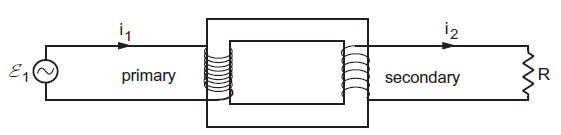
TRANSFORMER
A transformer is a device for converting high voltage into low voltage and vice versa, without change in power.
There are two types of transformers.
- Step up transformer : It converts low voltage into high voltage.
- Step down transformer : It converts high voltage into low voltage.
The principle of a transformer is based on mutual induction and a transformer always works on AC. The input is applied across primary terminals and output is obtained across secondary terminals.
The ratio of number of turns in secondary and primary is called the turn ratio
i.e.,  = turn ratio K.
If EP and ES are alternating voltages, IP and IS the alternating currents across primary and secondary terminals
respectively then, 
With Phase being 1800 , equation becomes
\(\frac{\varepsilon _s}{\varepsilon _p}=-\frac{N_s}{N_p} =\frac{I_p}{I_s} =k\)
Efficiency of transformer,
COMPARATIVE STUDY OF STEP-UP TRANSFORMER AND STEP-DOWN TRANSFORMER

POWER LOSSES IN A TRANSFORMER
- Copper loss. This is due to resistance of the winding of primary and secondary coil (I2 R)
- Iron loss or Eddy current loss.
- Loss due to leakage of magnetic flux.
- Hysteresis : Due to repeated magnetisation and demagnetisation of iron core.
- Humming loss : Due to vibration.
Inspite of all these losses, we have transformers with efficiency of 70% – 90%.