9.2 Single-slit Diffraction
Diffraction is appreciable if the wavelength is of the same order of magnitude as the opening (b) or bigger, i.e. λ ≥ b.
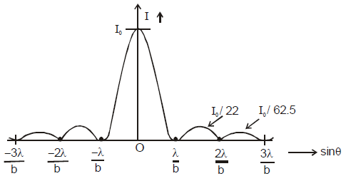
Central maximum is twice the width of other maxima, which are evenly separated.
Central maximum is about 20 times as intense as the other maxima.
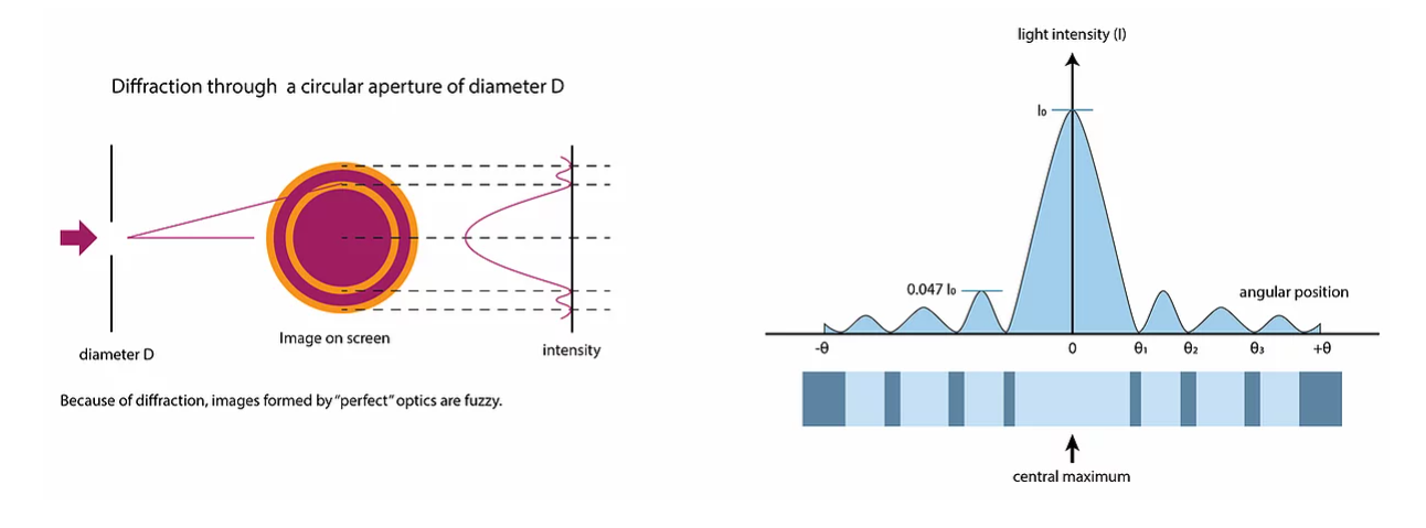
Variation of intensity with angle for a diffraction pattern
Central maximum is twice the width of other maxima, which are evenly separated.
Central maximum is about 20 times as intense as the other maxima.
Each successive maxima (excluding the central maximum) has less than half the previous one’s intensity.
Diffraction by a single rectangular slit
Huygen’s principle: You may always think on a wavefront as an infinite series of source points, generating secondary waves, which, summed together, equal the total wavefront.
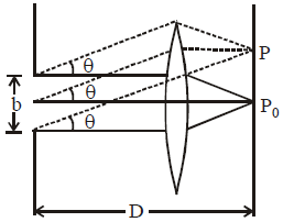
Single-slit diffraction explanation: “For two waves coming from the edges of the slit making an angle θ with the straight through, there is a path difference bsinθ. Waves from a point halfway along the slit will have a path difference of b/2 sinθ”. (Bowen-Jones & Homer, 2014)
Consequence: For each point in the bottom half of the slit, there will be a point in the upper half of the slit with a path difference of b/2 sinθ.
Small angle approximation: tanθ = sinθ = θ, and thus, b/2 sinθ = bθ/2 = λ/2, i.e. bθ = λ.
θ = s/D, where D is the distance between the slit and screen and s = distance of first minimum from center.
Destructive interference: When the path difference equals half the wavelength.
First minimum: θ = λ/b.
Additional minima: θ = nλ/b, n = 1, 2, 3…
Diffraction with laser is monochromatic.
Diffraction with white light: central maximum is white, fringes will be colored and blue diffracts the least.
9.3 Interference
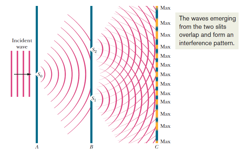
Double-slit interference
Sources must be exactly in phase, otherwise no interference pattern will be formed.
Destructive interference: If the path difference is a half-integral multiple of λ.
Path difference = (n +1/2)λ, n = 0, 1, 2…
Constructive interference: If the path difference is an integral multiple of λ.
Path difference = dsinθ = nλ, n = 0, 1, 2…, where θ is the angle between two primary maxima.
Intensity variation:
Slit widths of negligible size:
Bright fringes are equally bright and spaced.
Smaller slit separation: maxima are further apart.
Slit widths with real size: modulation by single-slit diffraction.
Constant fringe spaging, varying intensity.
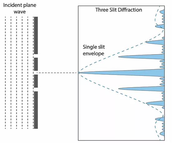
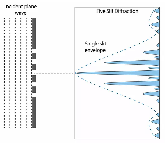
With N slits there are N-2 secondary maxima between primary maxima.
Intensity of the central maximum is N².
Primary maxima of the multiple-slit interference pattern are observed at the same angles as the corresponding two-slit pattern with the same slit separation.
As N increases:
Primary maxima become thinner and sharper.
Secondary maxima become unimportant.
Three slits:
Five slits:
Diffraction grating: large number of parallel slits, whose width we take to be negligible.
Uses: analyze wavelength of light, disperse white light into its component colors.
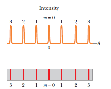
Maxima are sharp and bright, as there is a large number of slits causing constructive interference.
Spacing between the slits is small, and thus, there is no small angle approximation, as the angular separation of the maxima is very large. dsinθ = nλ, where n is known as the “order” and n = 0, 1, 2…, i.e. 0 order, 1st order, 2nd order…
Maximum order: Found using sinθ < 1, when d and λ are known.
Total number of orders: 2n + 1 (Counting “0 order” and the negative orders).
Lines per millimeter: diffraction grating is stated to have N lines per millimeter. This means that the separation of the slits is d = 1/N mm.
Diffraction grating with white light: Each successive visible spectrum repeats the order of the colors of the previous one, but less intense and more spread out. The central one is always white.
Interference may occur by:
Division of wavefronts: taking waves from different parts of the same wavefront, and thus, they are in phase. Called “non-localized”, as they may be found anywhere.
Division of amplitude: achieving interference using two waves that come from the same point on a wavefront. The source of waves must be much bigger than the slit used for division. Image produced by the two waves, each with a portion of the original one, is localized to one plane.
WAVE OPTICS
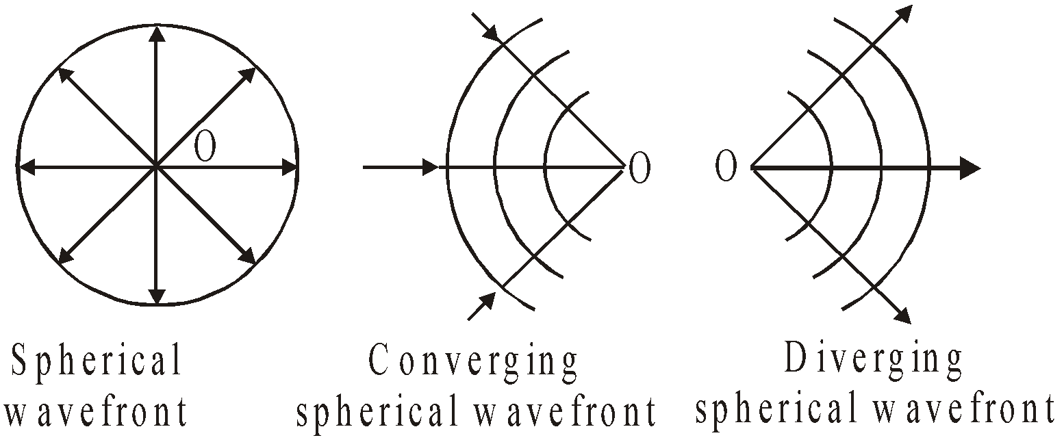
WAVEFRONT
- Spherical wavefront : A spherical wavefront is produced by a point source of light. This is because the locus of all such points which are equidistant from the point source will be a sphere. Spherical wavefronts are further divided into two headings: (i) converging spherical and (ii) diverging spherical wavefront.
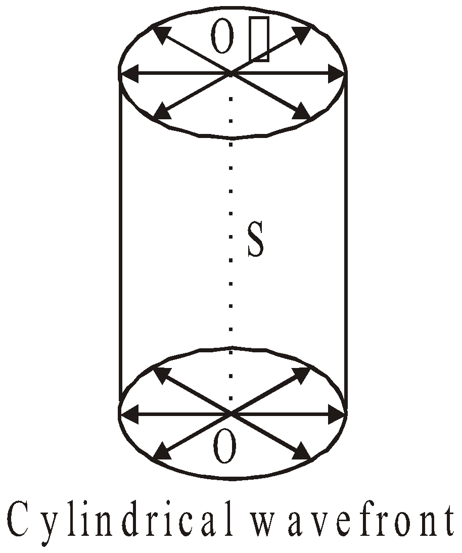
- Cylindrical wavefront : When the source of light is linear in shape such as a slit, the cylindrical wavefront is produced. This is because all the points equidistant from a line source lie on the surface of a cylinder.
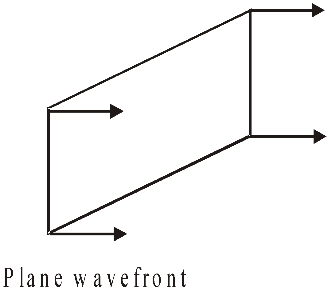
- Plane wavefront : A small part of a spherical or cylindrical wavefront due to a distant source will appear plane and hence it is called plane wave-front. The wavefront of parallel rays is a plane wavefront.
HUYGENS WAVE THEORY
- Each point source of light is a centre of disturbance from which waves spread in all directions.
- Each point on primary wavelets acts as a new source of disturbance and produces secondary wavelets which travel in space with the speed of light.
- The forward envelope of the secondary wavelets at any instant gives the new wavefront.
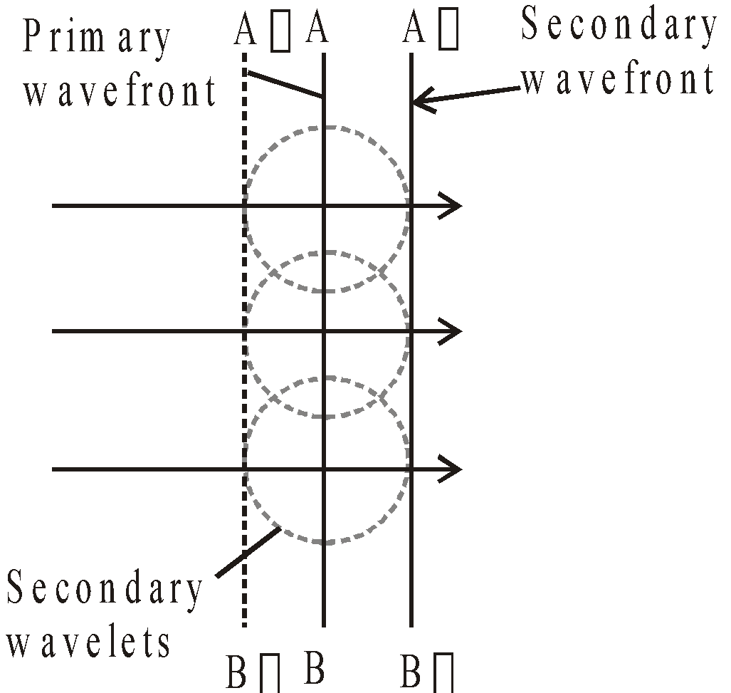
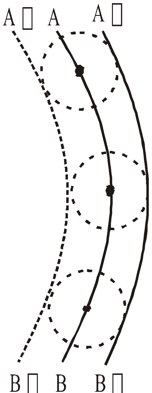
- In a homogeneous medium the wavefront is always perpendicular to the direction of wave propagation.
DRAWBACKS OF HUYGENS WAVE THEORY
- This theory cannot explain photoelectric effect, Compton, and Raman effect.
- Hypothetical medium in vacuum is not true imagination.
- The theory predicted the presence of back wave, which proved to be failure.
REFLECTION AND REFRACTION OF PLANE WAVES USING HUYGENS PRINCIPLE
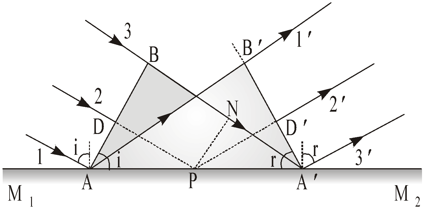
REFLECTION ON THE BASIS OF WAVE THEORY
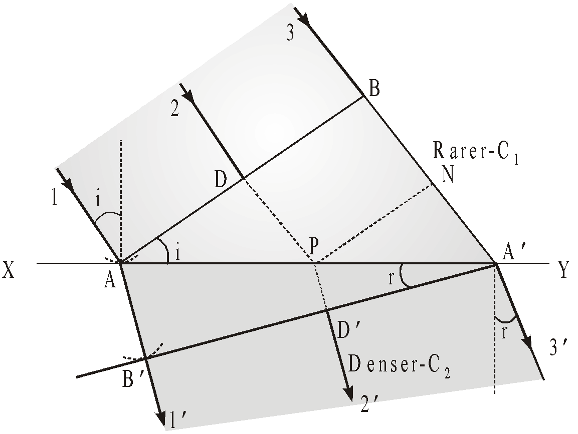
REFRACTION ON THE BASIS OF WAVE THEORY
- In 1873, Maxwell showed that light is an electromagnetic wave i.e. it propagates as transverse non-mechanical wave at speed c in free space given by
- There are some phenomenon of light like photoelectric effect, Compton effect, Raman effect etc. which can be explained only on the basis of particle nature of light.
- Light shows the dual nature i.e. particle as well as wave nature of light. But the wave nature and particle nature both cannot be possible simultaneously.
- Interference and diffraction are the two phenomena that can be explained only on the basis of wave nature of light.
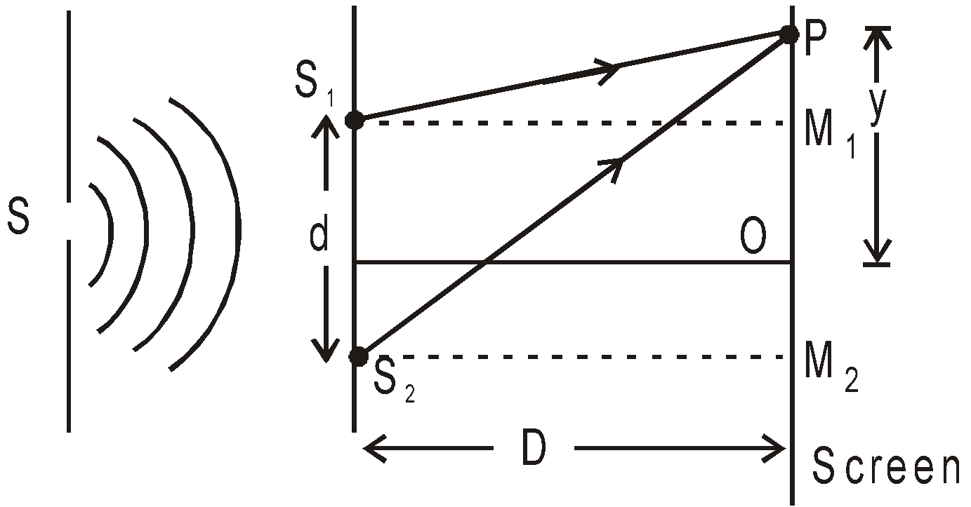
INTERFERENCE OF LIGHT WAVES AND YOUNG’S DOUBLE SLIT EXPERIMENT
 ….(3)
….(3)
(A) CONDITIONS FOR MAXIMUM & MINIMUM INTENSITY
(B) POSITION OF FRINGE
If![]() , then we obtain dark fringe at point P on the screen and corresponds to destructive interference. So from equation (4), the position of, nth dark fringe is
, then we obtain dark fringe at point P on the screen and corresponds to destructive interference. So from equation (4), the position of, nth dark fringe is
(C) SPACING OR FRINGE WIDTH
(D) CONDITIONS FOR SUSTAINED INTERFERENCE
- The two sources should be coherent i.e. they should have a constant phase difference between them.
- The two sources should give light of same frequency (or wavelength).
- If the interfering waves are polarized, then they must be in same state of polarization.
(E) CONDITIONS FOR GOOD OBSERVATION OF FRINGE
- The distance between two sources i.e. d should be small.
- The distance of screen D from the sources should be quite large.
- The two interfering wavefronts must intersect at a very small angle.
(F) CONDITIONS FOR GOOD CONTRAST OF FRINGE
- Sources must be monochromatic i.e. they emit waves of single wavelength.
- The amplitude of two interfering waves should be equal or nearly equal.
- Both sources must be narrow.
- As Intensity I is directly proportional to the square of amplitude, hence Intensity of resultant wave at P,

- Angular fringe-width

- The width of all interference fringes are same. Since fringe width β is proportional to λ, hence fringes with red light are wider than those for blue light.
- If the interference experiment is performed in a medium of refractive index μ instead of air, the wavelength of light will change from λ to
 .
.
- If a transparent sheet of refractive index μ and thickness t is introduced in one of the paths of interfering waves, then due to its presence optical path will become μt instead of t. Due to this a given fringe from present position shifts to a new position. So the lateral shift of the fringe,
- In Young’s double slit experiment (coherent sources in phase): Central fringe is a bright fringe. It is on the perpendicular bisector of coherent sources. Central fringe position is at a place where two waves having equal phase superpose.
- Young’s experiment with the white light will give white central fringe flanked on either side by coloured bands.
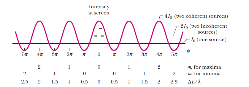
A plot of above equation, showing the intensity of a double-slit interference pattern as a function of the phase difference between the waves when they arrive from the two slits. I0 is the (uniform) intensity that would appear on the screen if one slit were covered.The average intensity of the fringe pattern is 2I0, and the maximum intensity (for coherent light) is 4I0.
COHERENCE
TEMPORAL COHERENCE
- The duration of this transition is about 10–9 to 10–10 sec. Thus the emitted wave remains sinusoidal for this much time. This time is known as coherence time (
 ).
). - Definite phase relationship is maintained for a length
 called coherence length.
- The spectral lines width
 is related to coherence length L and coherence time τc.
SPATIAL COHERENCE
METHODS OF OBTAINING COHERENT SOURCES
- By division of wavefront
- By division of amplitude.
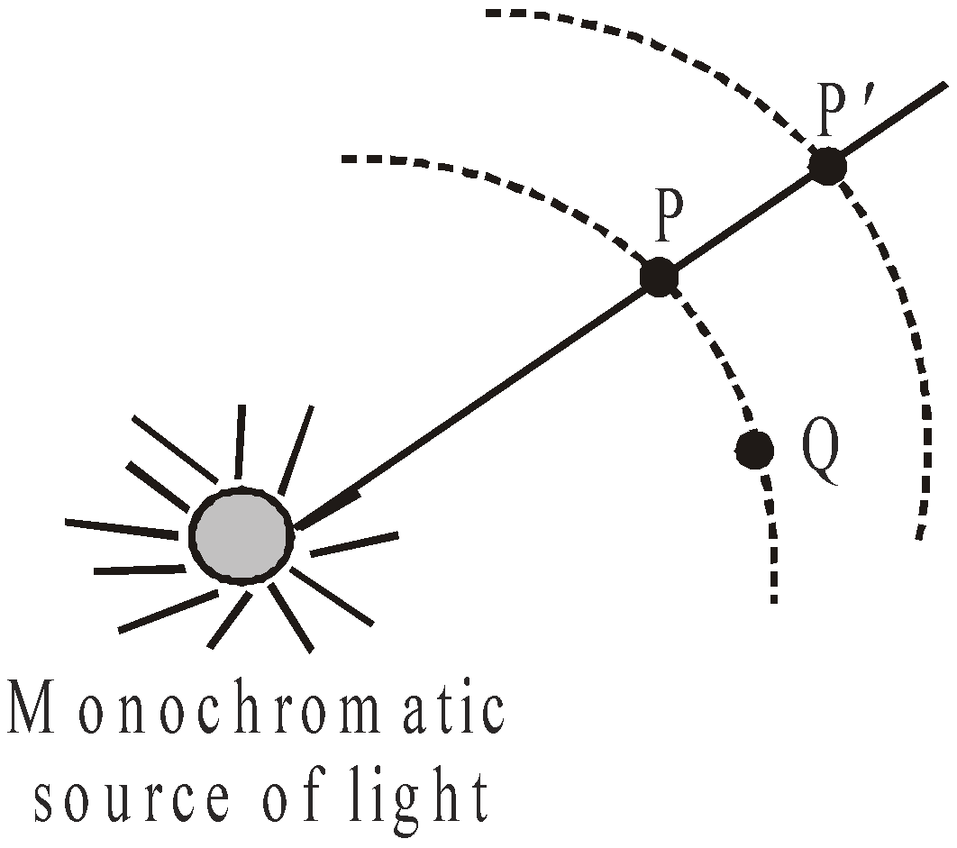
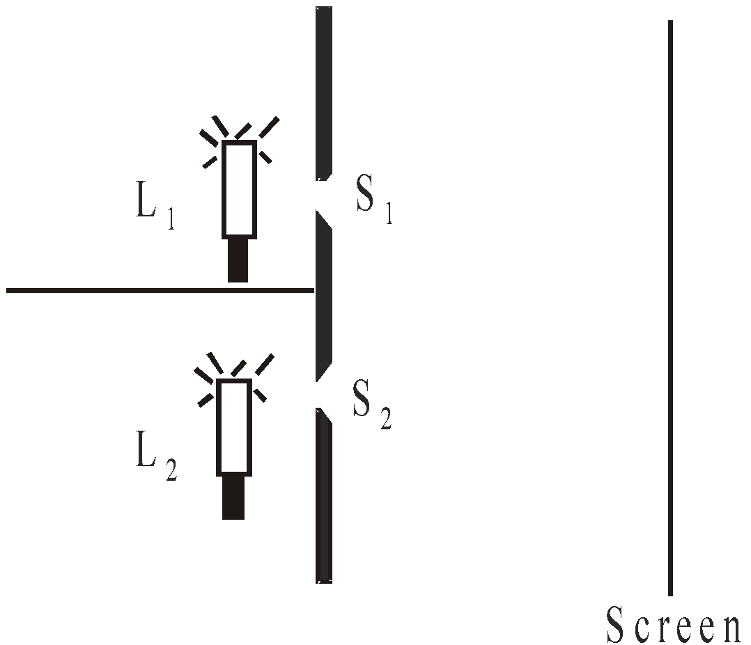
INCOHERENCE OF TWO CONVENTIONAL LIGHT SOURCES
LLOYD’S MIRROR
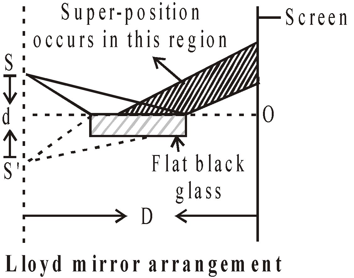
- If screen is moved so that, point O touches the edge of glass plate, the geometrical path difference for two wave trains is zero. The phase change of π radian on reflection at denser medium causes a dark fringe to be formed.
- The fringe width remains unchanged on introduction of transparent film.
- If the film is placed in front of upper slit S1, the fringe pattern will shift upwards. On the other hand if the film is placed in front of lower slit S2, the fringe pattern shifts downwards.
- This interference pattern is frequently seen in a ripple tank when one uses a wave train to demonstrate the law of reflection.
- In this case, fringe width

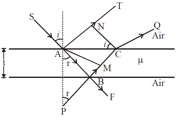
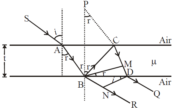
INTERFERENCE IN THIN FILMS
- reflected light
- transmitted light
INTERFERENCE DUE TO REFLECTED LIGHT
- If
 , where n = 0,1,2, …………..then constructive interference takes place and the film appears bright.
 - If
 , where n = 0, 1, 2, 3,………… then destructive interference takes place and the film appears dark.
INTERFERENCE DUE TO TRANSMITTED LIGHT
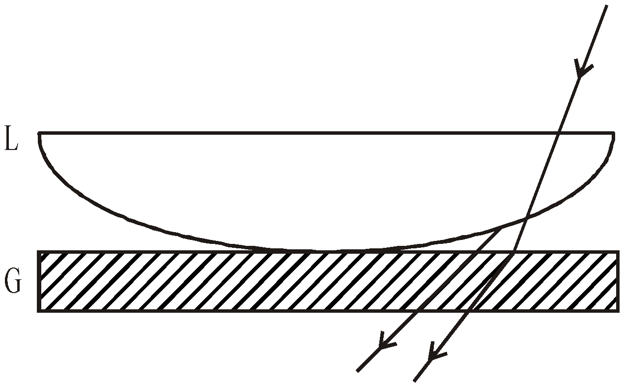
NEWTON’S RINGS
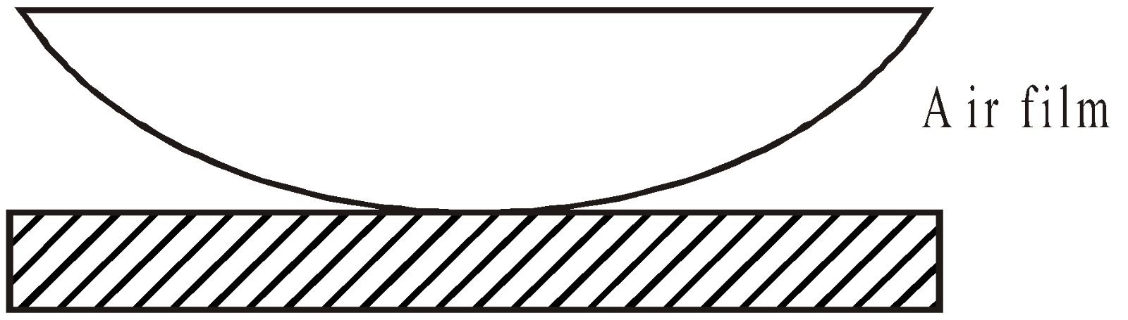
NEWTON’S RINGS BY REFLECTED LIGHT
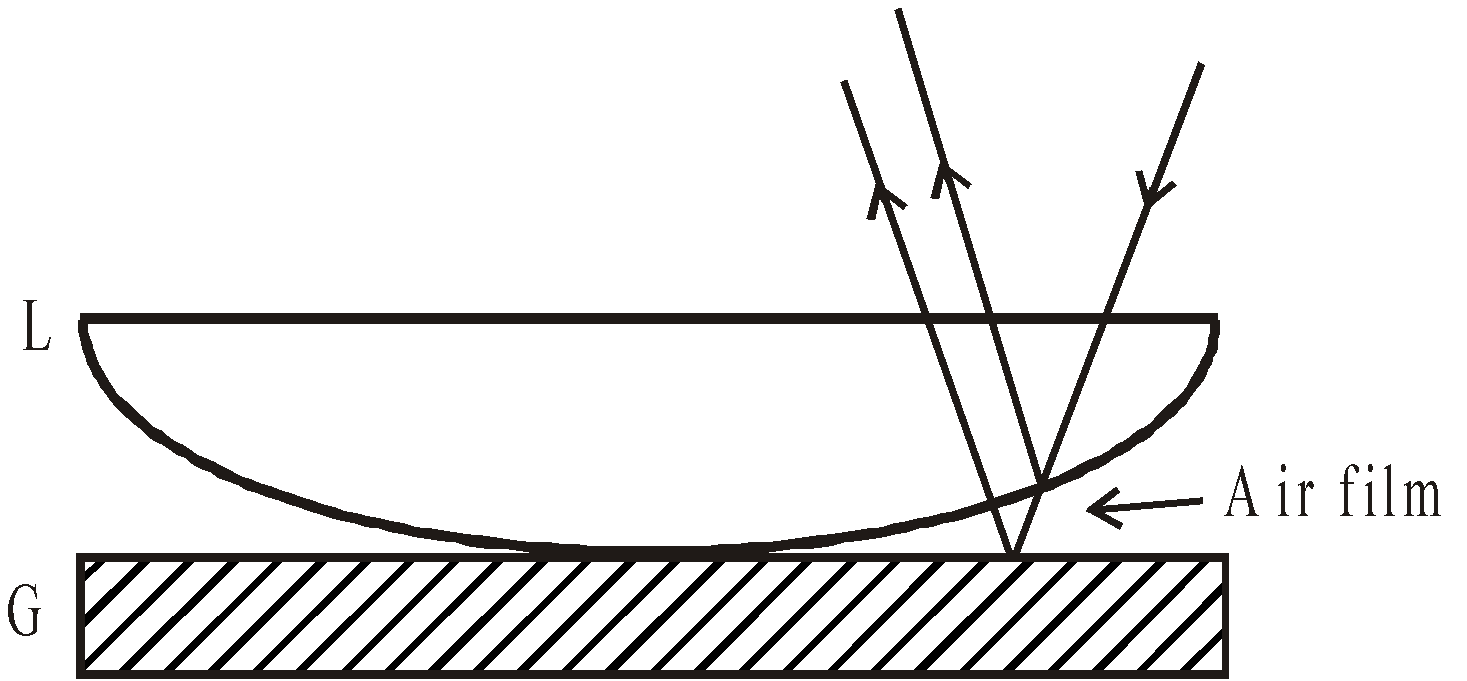
where R = radius of curvature of lens.
- The centre is dark and alternately dark and bright rings are produced.
- While counting the order of the dark rings 1, 2, 3, etc. the central ring is not counted. Therefore,
NEWTON’S RINGS BY TRANSMITTED LIGHT
- The centre is bright and alternately bright and dark rings are obtained.
- The ring pattern due to reflected light is just opposite to that of transmitted light.
- If Dn and Dn + m be the diameters of n th and (n + m)th dark rings then the wavelength of light used is given by
- If Dn = diameter of nth dark ring when air is present between the glass plate and the lens
DIFFRACTION
FRAUNHOFER DIFFRACTION BY SINGLE SLIT
- The points of the maximum intensity lie nearly midway between the successive minima. The amplitude E0‘ of the electric field at a general point P is
- The graph for the variation of intensity as a function of sinθ is as follows :
- The width of the central maxima is
 and angular width of central maxima is
 .
.
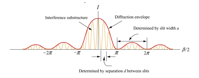
We have seen that the interference maxima occur when d sinθ = mλ . On the other hand, the condition for the first diffraction minimum is a sinθ = λ . Thus, a particular interference maximum with order number m may coincide with the first diffraction minimum. The value of m may be obtained as:
\(\frac{d \; sin \theta}{a\; sin\theta}=\frac{m \lambda}{ \lambda}\)
or
\(m = \frac{d}{a}\)
Hence \(mth \) fringe will not be seen.
FRAUNHOFER DIFFRACTION BY A CIRCULAR APERTURE
- The 1st dark ring is formed by the light diffracted from the circular aperture at an angle θ with the axis where
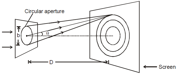
- If the screen is at a distance D (D >> b) from the circular aperture, the radius of the 1st dark ring is,

- If the light transmitted by the hole is converged by a converging lens at the screen placed at the focal plane of the lens, the radius of the 1st dark ring is

Diffraction Gratings
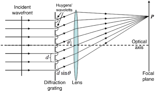
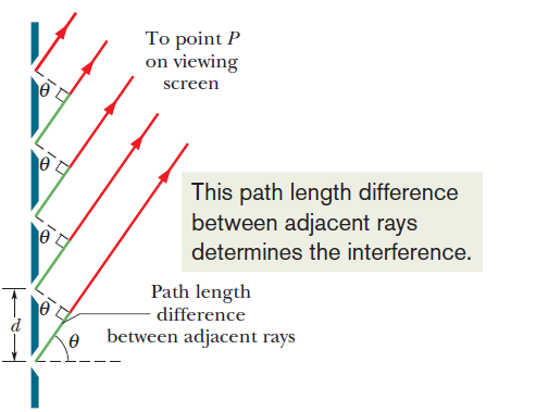
The separation d between rulings is called the grating spacing. (If N rulings occupy a total width w, then d = w/N.) The path length difference between adjacent rays is again d sin u , where u is the angle from the central axis of the grating (and of the diffraction pattern) to point P. A line will be located at P if the path length difference between adjacent rays is an integer number of wavelengths :
\(d sin\theta = m \lambda\) or \(sin\theta=\frac{m\lambda}{d}\) for \(m= 0,1,2,3\) (maxima – line)
where \(\lambda\) is the wavelength of the light. Each integer m represents a different line; hence these integers can be used to label the lines, as in below figure. The integers are then called the order numbers, and the lines are called the zeroth-order line (the central line, with m = 0), the first-order line (m = 1), the second-order line (m = 2), and so on.
Resolving Power of grating
To resolve lines whose wavelengths are close together (that is, to make the lines distinguishable), the line should also be as narrow as possible. Expressed otherwise, the grating should have a high resolving power R, defined as
\(R=\frac{\lambda_{avg}}{\Delta \lambda}\)
here \(\lambda_{avg}\) is the mean wavelength of two emission lines that can barely be recognized as separate, and \(\Delta \lambda\) is the wavelength difference between them.
Also resolving power of a grating is given by the simple expression
\(R= Nm\)
Hence \(R= Nm =\frac{\lambda_{avg}}{\Delta \lambda}\)
DIFFERENCE BETWEEN INTERFERENCE AND DIFFRACTION OF LIGHT

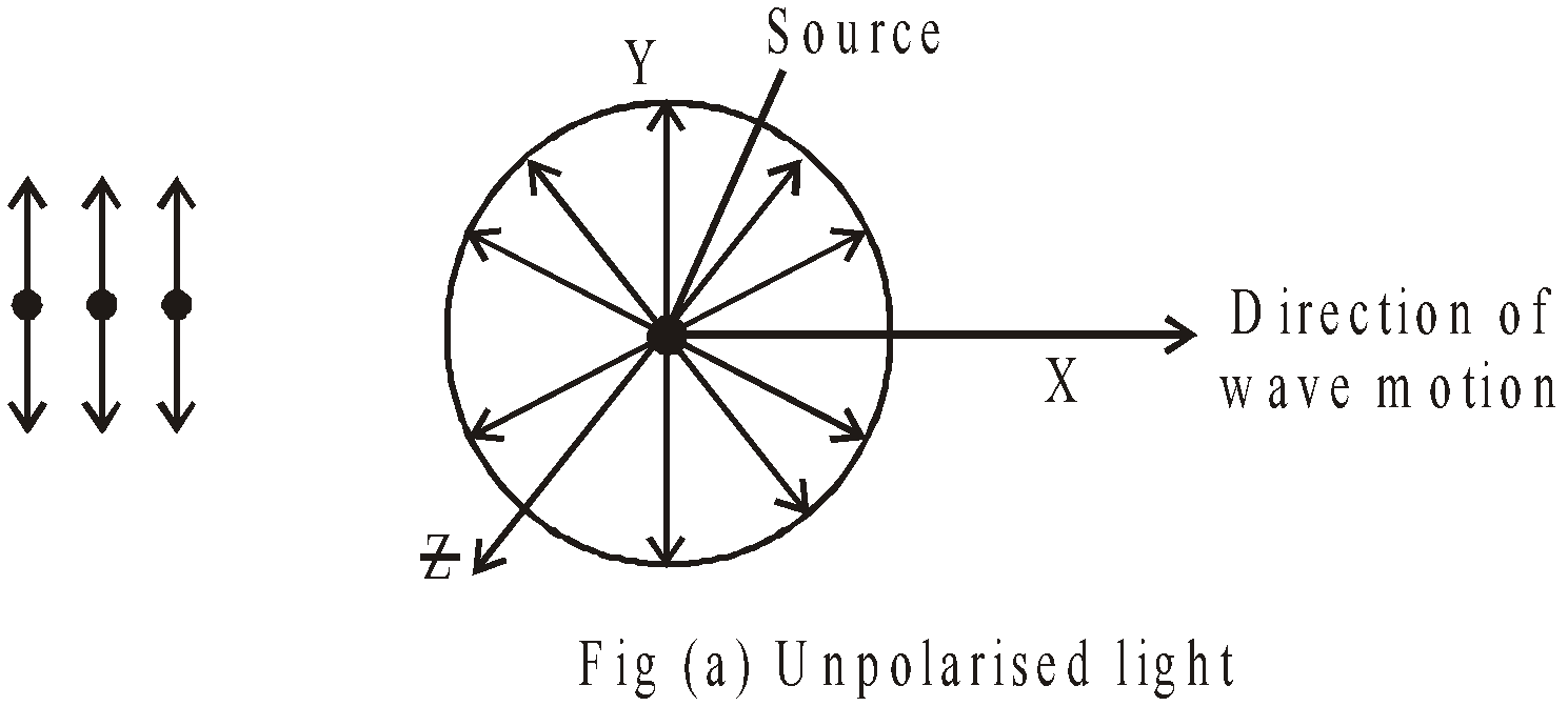
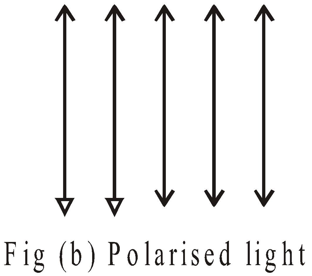
POLARISATION
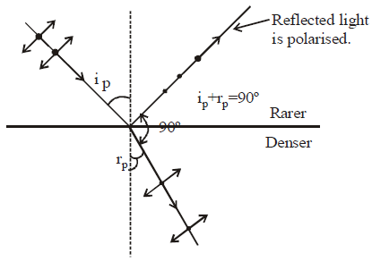
POLARIZATION BY REFLECTION (BREWSTER’S LAW)
LAW OF MALUS
- Plane polarized : oscillating electric field is in a single plane.
- Circularly polarized : tip of oscillating electric field describes a circle.
- Elliptically polarized : tip of oscillating electric field describes an ellipse.
RESOLVING POWER OF AN OPTICAL INSTRUMENT
DOPPLER’S EFFECT FOR LIGHT WAVES